Security barrier system

a security barrier and gate technology, applied in the direction of traffic restrictions, wing accessories, roads, etc., can solve the problems of system protection against the potential cutting action of the pipe end, and achieve the effects of reducing wear damage, increasing strength, and uniform distribution of load

Active Publication Date: 2011-10-11
GLOBAL GRAB TECH INC
View PDF35 Cites 11 Cited by
  • Summary
  • Abstract
  • Description
  • Claims
  • Application Information

AI Technical Summary

Benefits of technology

[0007]This invention provides an an anti-ram vehicle barrier. A barrier assembly may be attached to a host swinging or sliding gate or other barrier section to improve the barrier, thereby reinforcing the gate or other barrier section and evenly distributing loading and reducing wear damage to various components of the apparatus. The invention may also be a stand alone barrier assembly. The invention also improves superposts or posts used in barrier assemblies by providing passive engagement devices and providing increased strength to barrier assembly posts and superposts.

Problems solved by technology

One weakness of both the prior art devices is that they permit the full force of impact to bear as a concentrated load on a single point in the cable.
Additionally, these systems do not provide protection against the potential cutting action of the pipe ends or the standoffs on the wire rope when either device experiences dynamic stresses such as those that result from the impact of an automobile against such a device.

Method used


Image

  • Security barrier system
  • Security barrier system
  • Security barrier system

Examples


Embodiment Construction

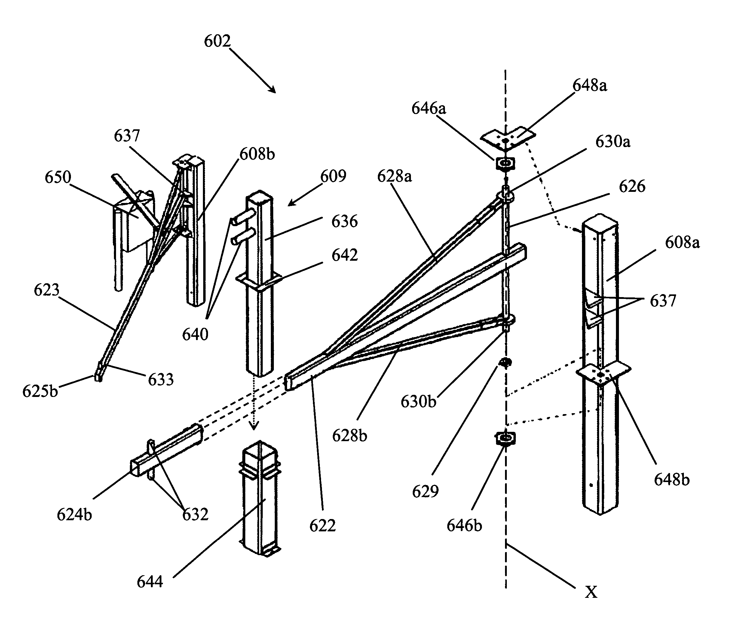
[0047]The detailed description that follows describes various embodiments of the invention. The embodiments are described for exemplary purposes only. It should be understood that the various embodiments discussed below may be improvements to existing security structures or entirely whole new security structures. Moreover, it should be understood that the various embodiments of security structure improvements and new security structures may be used with or include swing gates, sliding gates, vertically lowered or raised gates, and other gate mechanisms known to those skilled in the art.

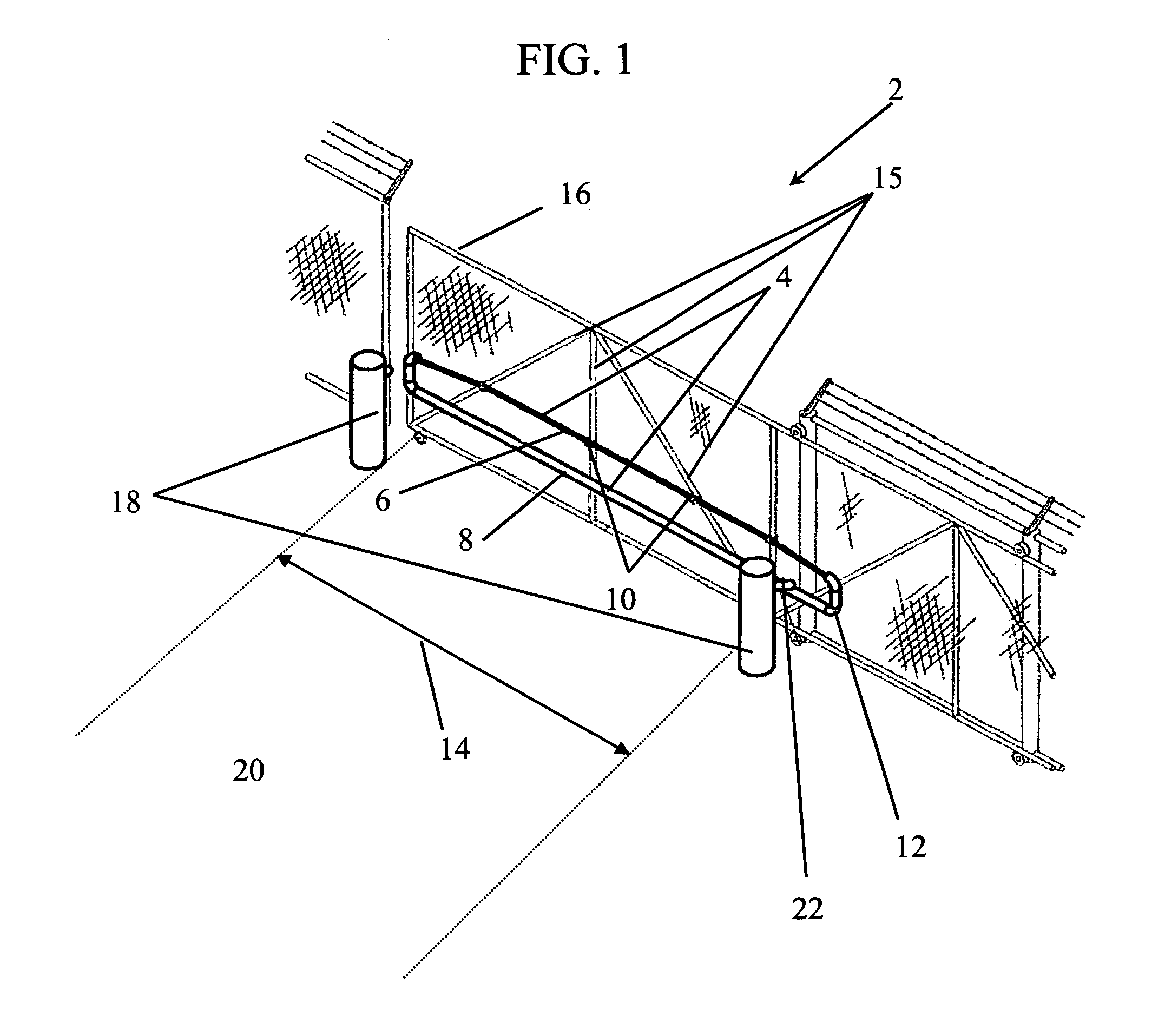
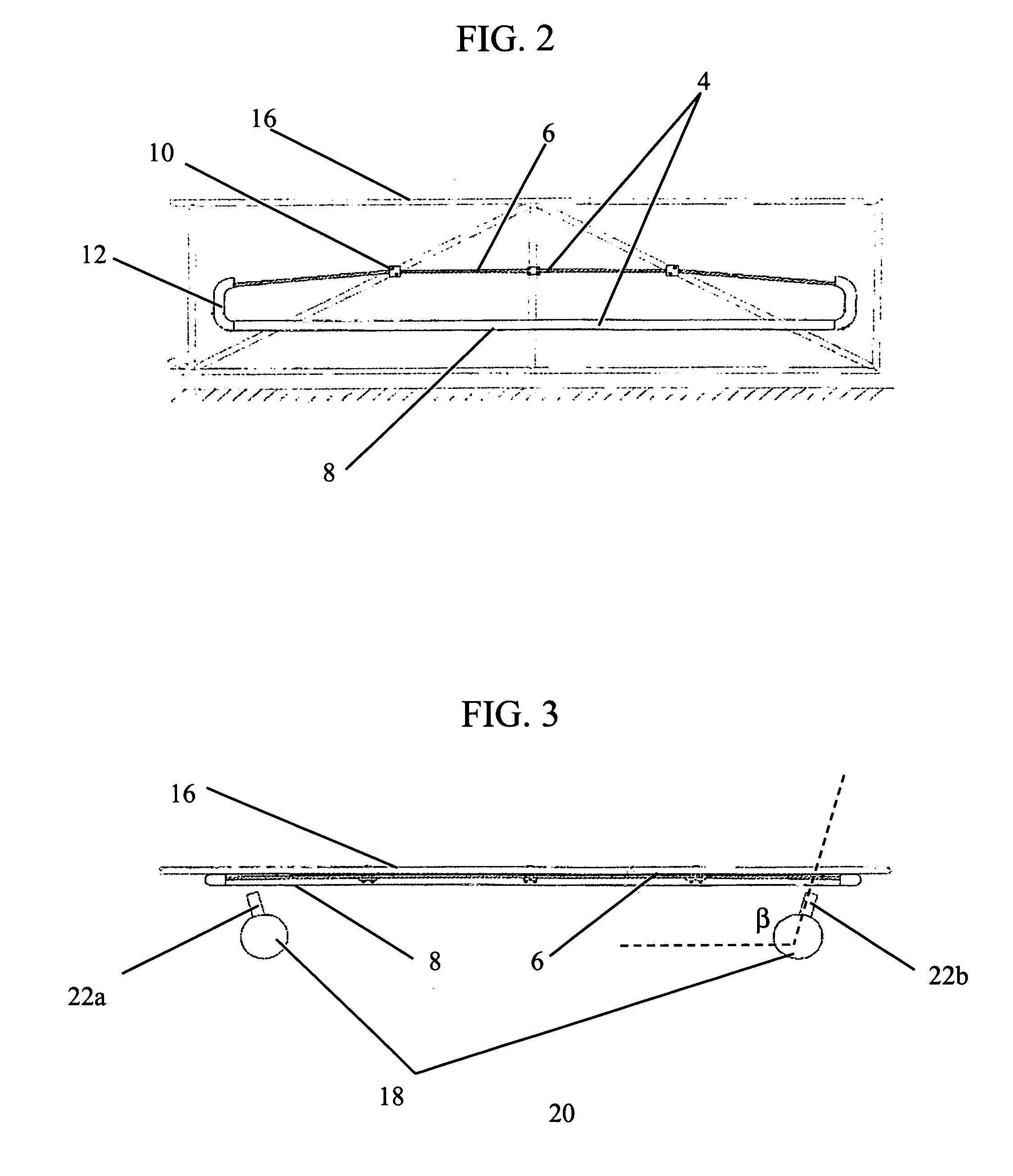
[0048]An overview of a preferred embodiment of the invention is shown in FIG. 1, displaying a security barrier apparatus 2. The security barrier apparatus 2 is further broken down into an attachable assembly 4 wherein a cable, preferably a multi-strand flexible steel cable 6 from between about 1 inch to about 2 inches in diameter, is routed through a structural member 8. Those skilled in the art appre...


PUM


Abstract

A security barrier apparatus which may be used in conjunction with an existing security gate or may be used as a stand-alone security barrier gate. The system uses a passive restraining device comprising a bollard having at least one catch horn extending therefrom which engages a corresponding structure on the gate to restrain the gate when impacted.

Description

[0001]The present application is a continuation-in-part of U.S. application Ser. No. 10 / 777,932, filed Feb. 12, 2004 now U.S. Pat. No 7,121,041.FIELD[0002]This invention relates to the field of gate systems and gate reinforcement systems and techniques. More particularly, the invention relates to an apparatus for replacing or for improving host gate systems.BACKGROUND OF THE INVENTION[0003]With heightened security requirements at facilities across the country and overseas, an increased need has developed for devices that can easily operate as gates or gated barriers and meet necessary crash barrier requirements. Such devices may be entirely stand-alone systems or the devices may act as an upgrade or improvement to previously existing gates or gated barriers.[0004]A prior art device in use at Argonne National Laboratory since the mid-1980s provides an approach that has been improved with the present invention. The prior art device is simply a straight steel pipe with a wire rope cabl...

Claims


Application Information

Patent Timeline
Patent Type & Authority Patents(United States)
IPC IPC(8): E01F13/00E01F13/04
CPCE01F13/048
Inventor ANDERSON, JOE W.KAMINSKY, VICTOR J.LANCASTER, III, THOMAS A.HORNSTRA, DOUGLAS J.LIGHT, MICHAEL W.POWERS, JAMES C.SCHENK, RICHARD W.
Owner GLOBAL GRAB TECH INC
Why Eureka
Try Eureka