Exposure apparatus and exposure method, and device manufacturing method
a technology of immersion exposure apparatus and manufacturing method, which is applied in the direction of photomechanical treatment, printing, instruments, etc., can solve problems such as defective exposure, and achieve the effect of suppressing defective exposure in the immersion exposure apparatus
- Summary
- Abstract
- Description
- Claims
- Application Information
AI Technical Summary
Benefits of technology
Problems solved by technology
Method used
Image
Examples
first embodiment
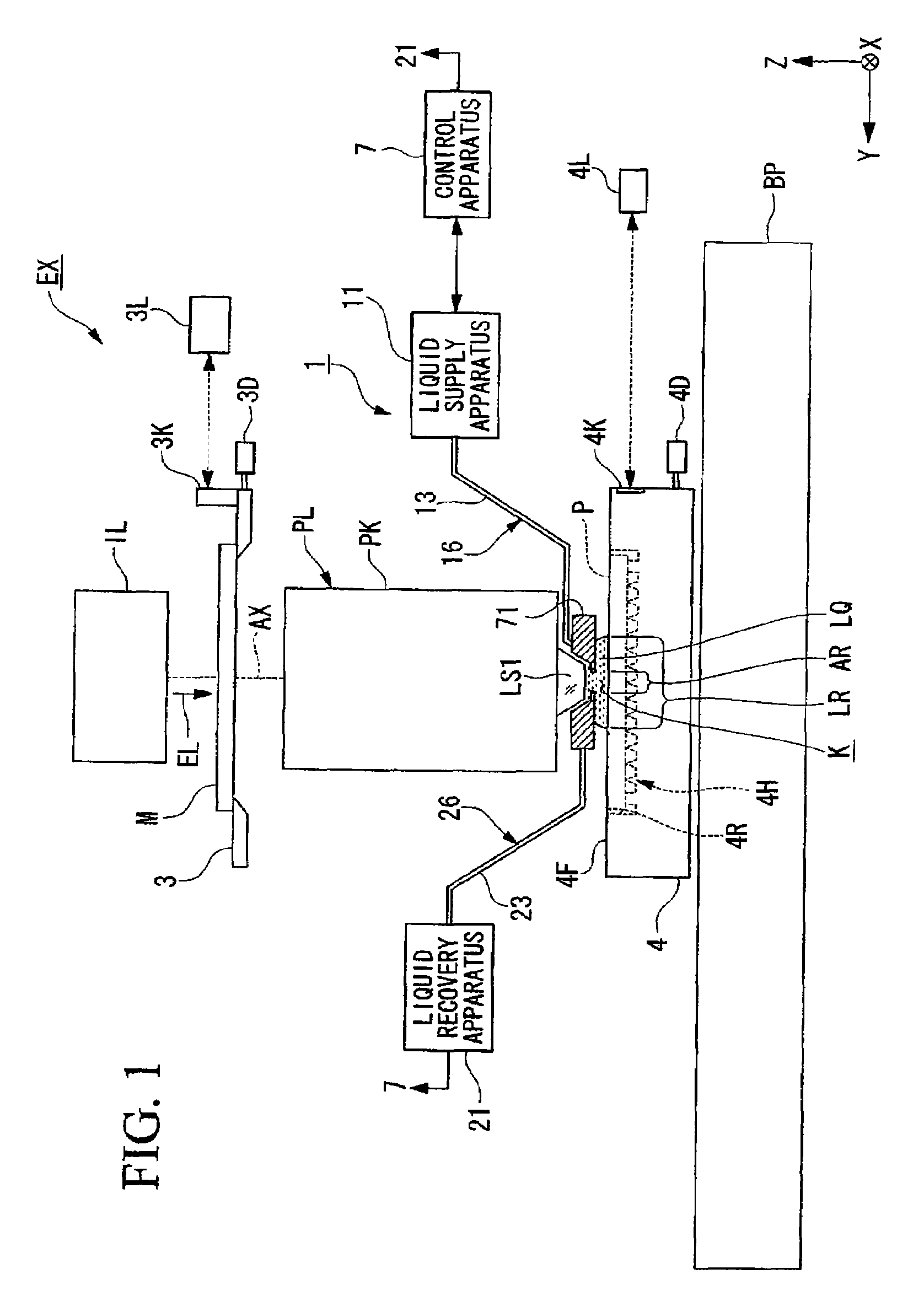
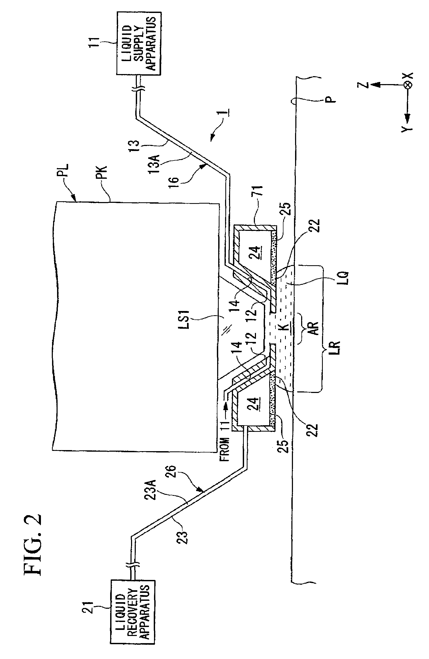
[0033]A first embodiment will be explained. FIG. 1 is a schematic block diagram showing an exposure apparatus EX according to the first embodiment. In FIG. 1, the exposure apparatus EX includes: a mask stage 3 capable of holding and moving a mask M; a substrate stage 4 that has a substrate holder 4H for holding a substrate P and that is capable of holding and moving the substrate P held in the substrate holder 4H; an illumination optical system IL for illuminating the mask M held on the mask stage 3 with exposure light EL; a projection optical system PL for projecting a pattern image of the mask M illuminated by the exposure light EL onto the substrate P; and a control apparatus 7 for controlling the operation of the entire exposure apparatus EX. The substrate here includes one in which a film of a sensitive material (photoresist), a protection film (top coat film) and / or an anti-reflection film is spread on a base material such as a semiconductor wafer or the like. The mask include...
second embodiment
[0067]Next is a description of a second embodiment with reference to FIG. 4. In the following description, components the same as or similar to those of the aforementioned embodiment are denoted by the same reference symbols, and description thereof is simplified or omitted. In the aforementioned embodiment, the amount of the predetermined substance mixed into the liquid LQ that is supplied via the supply port 12 to the optical path space K of the exposure light EL between the bottom surface of the first optical element LS1 and the surface of the substrate P is set to be not greater than the predetermined value. However, as is disclosed in PCT International Patent Publication No. WO 2004 / 019128, an amount of the predetermined substance that is mixed in the liquid LQ into the optical path space on the object plane side (the mask M side) of the first optical element LS1 can be set to be not greater than the predetermined value.
[0068]In FIG. 4, an exposure apparatus EX includes an imme...
third embodiment
[0073]Next is a description of a third embodiment. In the following description, components the same as or similar to those of the aforementioned embodiments are denoted by the same reference symbols, and description thereof is simplified or omitted.
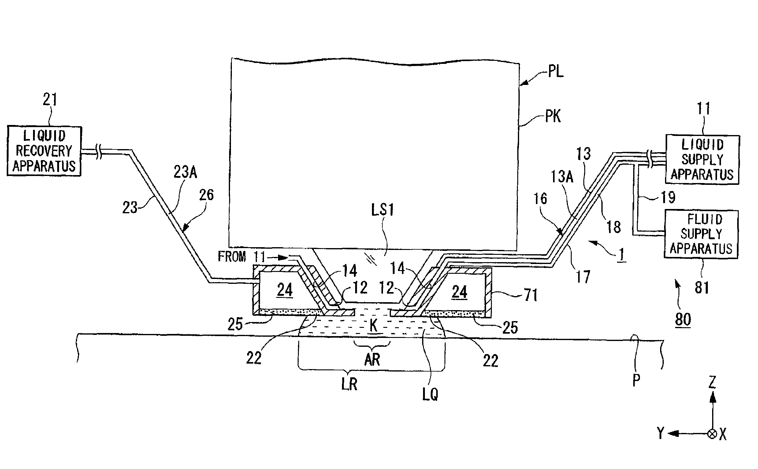
[0074]FIG. 5 shows a main part of an exposure apparatus EX according to a third embodiment. Similarly to the aforementioned embodiments, the exposure apparatus EX includes: a nozzle member 71 that has a supply port 12 and a recovery port 22; a liquid supply apparatus 11 for supplying a liquid LQ to the supply port 12 via a passage 13A of a supply pipe 13 and a first passage 14; and a liquid recovery apparatus 21 for recovering the liquid LQ that has been recovered from the recovery port 22 via a second passage 24 and a passage 23A of a recovery pipe 23. The supply pipe 13 forms a supply passage 16 for supplying the liquid LQ to the supply port 12.
[0075]The supply pipe 13 is permeable to a predetermined gas. The supply pipe 13 allows a ga...
PUM
 Abstract
Description
Claims
Application Information
 - R&D
- Intellectual Property
- Life Sciences
- Materials
- Tech Scout
- Unparalleled Data Quality
- Higher Quality Content
- 60% Fewer Hallucinations
Browse by: Latest US Patents, China's latest patents, Technical Efficacy Thesaurus, Application Domain, Technology Topic, Popular Technical Reports.
© 2025 PatSnap. All rights reserved.Legal|Privacy policy|Modern Slavery Act Transparency Statement|Sitemap|About US| Contact US: help@patsnap.com


