Packaging or container with optical indicator

a technology of optical indicators and packaging, applied in the direction of material testing goods, testing food, instruments, etc., can solve the problems of relatively complex optical systems, recording and measuring images, and sophisticated calculations, and achieve the effect of cheap production

Inactive Publication Date: 2011-08-16
QUALISENSE TECH
View PDF6 Cites 0 Cited by
  • Summary
  • Abstract
  • Description
  • Claims
  • Application Information

AI Technical Summary

Benefits of technology

[0010]c) an optical system having an optical axis and enabling observation of the object when illuminated by diffuse light, via the enclosure filled with the fluid.
[0030]Contrary to methods of measurement, the designer of an optical indicator in accordance with the invention has previous knowledge of the optical parameter both in the reference state and in the changed state of the fluid, so that he can design the optical system of the indicator accordingly to make the changed state of the fluid highly distinguishable. Therefore, the indicator may be adjusted for easy identification of a small predetermined change of the optical parameter without measuring it.
[0033]The optical indicator of the present invention is miniature, simple, reliable and cheap in production. It may be manufactured by injection-molding from common polymers and may even be made disposable. The optical indicator may be used in a wide variety of applications pertinent to detection of changes in the state of liquids, gases, mixtures, suspensions and the like, such as production, storage, packaging and monitoring of chemicals, oil, medicines, food, drinks, water, etc.

Problems solved by technology

Such methods require relatively complex optical systems, recording and measurement of images and sophisticated calculations in order to determine accurately a change in the refraction index of the liquid.

Method used


Image

  • Packaging or container with optical indicator
  • Packaging or container with optical indicator
  • Packaging or container with optical indicator

Examples


Embodiment Construction

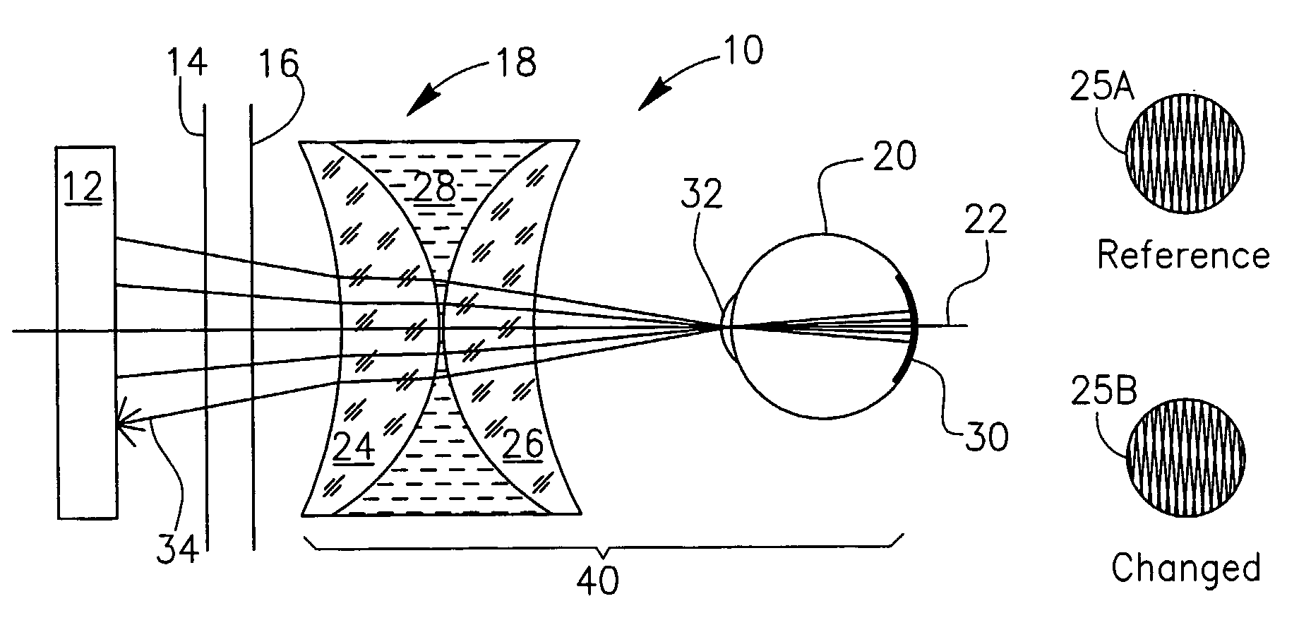
[0049]With reference to FIG. 1, there is shown an exemplary optical arrangement 10 for an optical indicator in accordance with the present invention. The optical arrangement 10 comprises two gratings 14 and 16 that may be illuminated by ambient light or (optionally) by a light from a diffuse light source 12. The arrangement 10 further comprises a transparent enclosure 18 with an axis 22 coinciding with the direction of observation. The axis 22 passes through the gratings 14 and 16, the enclosure 18 and the eye 20 of the observer. The gratings 14 and 16 are substantially parallel gratings and are both generally perpendicular to the axis 22. However, it is noted that the gratings 14 and 16 need not obligatorily be parallel gratings and that some embodiments of the invention may use non-parallel gratings.

[0050]The light source 12 may be any common fluorescent or incandescent lamp with or without a diffuser (not shown), but any other suitable source for providing diffused light, may be ...


PUM

PropertyMeasurementUnit
index of refractionaaaaaaaaaa
transparentaaaaaaaaaa
optical poweraaaaaaaaaa

Abstract

An optical indicator (130) for identification of a changed state of a fluid with respect to a reference state of the same fluid, or for monitoring or checking or authenticating a fluid. The fluid has an optical parameter that changes with the change of the state of the fluid. The optical indicator (130) may be attached to or integral with a container or packaging (132) for the fluid. The indicator (130) includes a cavity configured to be filed with the fluid such that the fluid filled cavity forms a variable optical element having an optical performance that varies depending on the changeable fluid's optical parameter. The fluid filled cavity coupled to other optical components of the indicator provides an image that may be compared to a reference image to detect a change of at least one optical property of the fluid as compared to the reference fluid. The comparison may be performed visually or by a suitable detector. The comparison may include automated processing of the detector's output signal(s).

Description

CROSS-REFERENCE TO RELATED APPLICATIONS[0001]This application is a National Phase Application of PCT International Application No. PCT / IL2005 / 000409, entitled “Packaging or Container with Optical Indicator”, International Filing Date Apr. 19, 2005, published on Nov. 3, 2005 as International Publication No. WO 2005 / 101971, which in turn claims priority from US Provisional Patent Application No. 60 / 563,463, filed Apr. 20, 2004, both of which are incorporated herein by reference in their entirety.FIELD OF THE INVENTION[0002]This invention relates generally to indicators of a condition of a fluid based on optical properties of the fluid and to packaging or containers including such optical indicators and methods of constructing them.BACKGROUND OF THE INVENTION[0003]U.S. Pat. No. 4,569,590 to Karney describes a system for determining unknown index of refraction of a sample fluid with reference to the refraction index of a known reference fluid. The system comprises a collimated light sou...

Claims


Application Information

Patent Timeline
Patent Type & Authority Patents(United States)
IPC IPC(8): G01N21/41G01N21/45
CPCG01N21/45G01N21/77G01N33/04G01N2021/456G01N2021/7776G01N2021/7779
Inventor GAN, LIVNE
Owner QUALISENSE TECH
Why Eureka
Try Eureka