
Method for producing active glass nanoparticles by laser ablation

a technology of active glass and laser ablation, which is applied in the field of manufacturing nanoparticles, can solve the problems of exceeding any currently available technology, and achieve the effect of high efficiency

Inactive Publication Date: 2011-07-26
RGT UNIV OF CALIFORNIA
View PDF9 Cites 24 Cited by
  • Summary
  • Abstract
  • Description
  • Claims
  • Application Information

AI Technical Summary

Benefits of technology

The present invention is about a method for producing active glass nanoparticles that show upconversion. This is done by using a high repetition-rate, ultra-short pulse duration laser to ablate the glass substrate and collect the nanoparticles that are ejected. The nanoparticles have been found to have a small size and bright upconversion green emission. This makes them useful for bio imaging and light emitting devices. The method can be carried out in either a liquid or gaseous environment and can involve the use of an Erbium-doped material or Bi2O3 based Er-doped glass material. The nanoparticles can be collected on silicon or glass substrates or into a downstream fluidic system. Overall, this invention provides a more efficient and effective way to produce active glass nanoparticles with upconversion properties.

Problems solved by technology

This capability exceeds any currently available technology.

Method used


Image

  • Method for producing active glass nanoparticles by laser ablation
  • Method for producing active glass nanoparticles by laser ablation
  • Method for producing active glass nanoparticles by laser ablation

Examples


Embodiment Construction

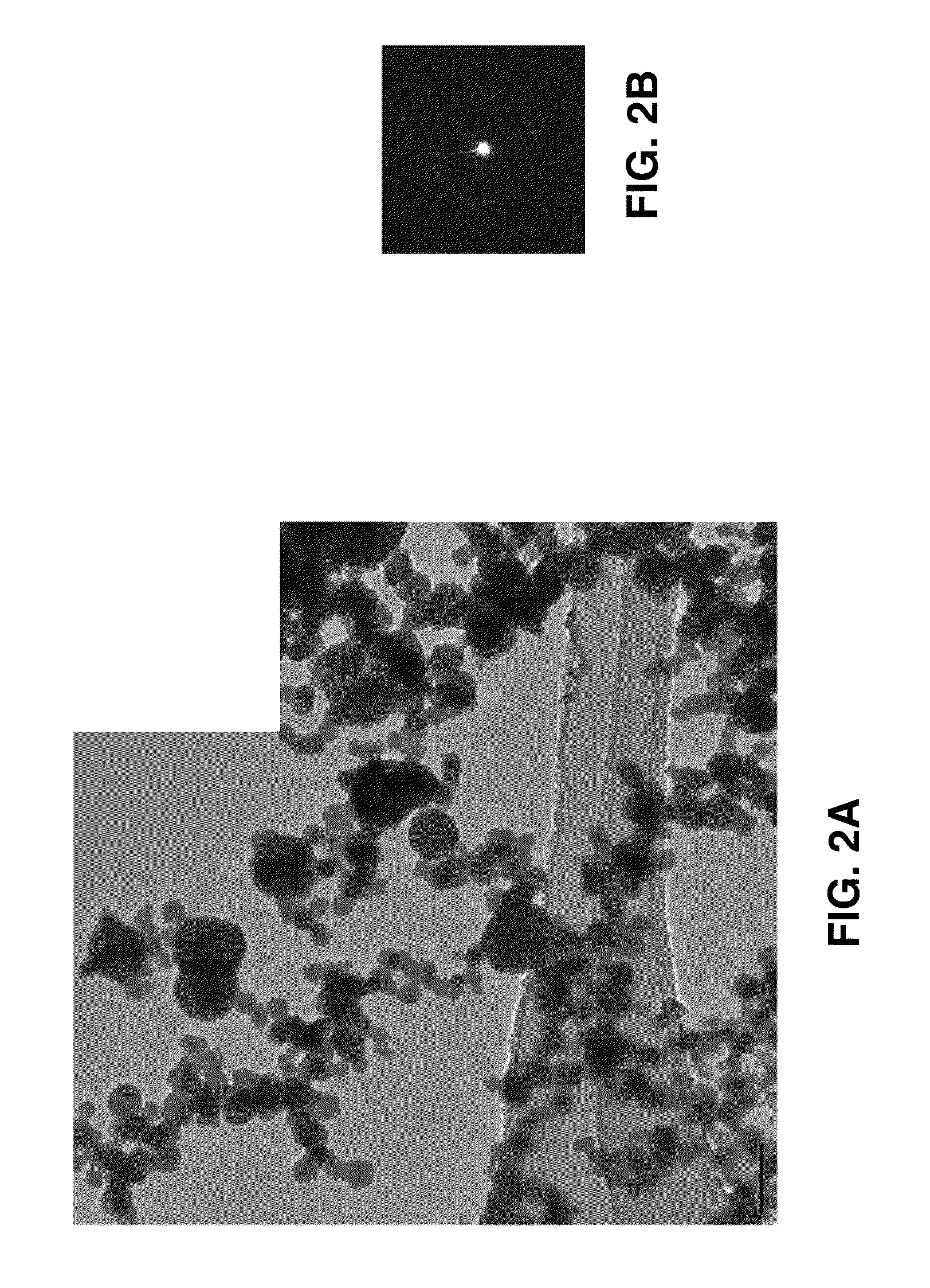
[0027]Referring more specifically to the drawings, for illustrative purposes the present invention is embodied in the apparatus generally shown in FIG. 1 through FIG. 5. It will be appreciated that the apparatus may vary as to configuration and as to details of the parts, and that the method may vary as to the specific steps and sequence, without departing from the basic concepts as disclosed herein.

[0028]By way of example, and not of limitation, erbium (Er) doped Bismuth (Bi) oxide glasses were prepared by melting mixed powders in a platinum crucible. The obtained glasses were cut and polished into optically smooth surfaces. A high repetition rate ultrashort pulsed-laser (IMRA America, FCPA μJewel, ˜375 fs pulse width at 1045 nm wavelength, 5 MHz maximum repetition rate at ˜100 nJ pulse energy) was chosen to generate nanoparticles by ablating the base glass material. In this example, the laser pulses at 1 MHz repetition rate and ˜500 nJ pulse energy were focused on the sample top s...


PUM

PropertyMeasurementUnit
mean particle diameteraaaaaaaaaa
visible wavelengthsaaaaaaaaaa

Abstract

A method for producing active glass nanoparticles that exhibit upconversion is described. The method employs pulsed-laser ablation of an active glass substrate using, for example, a high repetition rate ultra-short pulse duration laser under normal atmospheric conditions or in a liquid environment.

Description

CROSS-REFERENCE TO RELATED APPLICATIONS[0001]This application claims priority from, and is a 35 U.S.C. §111(a) continuation of, co-pending PCT international application serial number PCT / US2008 / 052846 filed on Feb. 1, 2008, incorporated herein by reference in its entirety, which claims priority from U.S. provisional application No. 60 / 887,872, filed on Feb. 2, 2007, incorporated herein by reference in its entirety, and from U.S. provisional application Ser. No. 60 / 888,688, filed on Feb. 7, 2007, incorporated herein by reference in its entirety.[0002]This application is also related to PCT International Publication No. WO 2008 / 118,536 which was published on Oct. 2, 2008 and republished on Dec. 11, 2008, each of which is incorporated herein by reference in its entirety.STATEMENT REGARDING FEDERALLY SPONSORED RESEARCH OR DEVELOPMENT[0003]This invention was made with Government support under Grant No. DMI-0556363, awarded by the National Science Foundation. The Government has certain ri...

Claims


Application Information

Patent Timeline
Patent Type & Authority Patents(United States)
IPC IPC(8): B29C35/08
CPCB82Y30/00C01G29/00C03B19/1005C03C4/12C03C12/00C03C23/0025C01P2002/52C01P2004/04C01P2004/51C01P2004/64Y10S977/889Y02P40/57
Inventor HIROMATSU, KUNIAKIHWANG, DAVID JENGRIGOROPOULOS, COSTAS P.
Owner RGT UNIV OF CALIFORNIA
Learn More