High performance imaging system for diffuse optical tomography and associated method of use

a technology of optical tomography and imaging system, which is applied in the field of high-performance imaging system for diffuse optical tomography and associated methods of use, can solve the problems of unmet challenges, limited lateral resolution of type of system and use of nearest neighbor optode pairs, and significant scanner noise, and achieve high dynamic range, high speed, and high performance

Active Publication Date: 2011-07-19
WASHINGTON UNIV IN SAINT LOUIS
View PDF13 Cites 267 Cited by
  • Summary
  • Abstract
  • Description
  • Claims
  • Application Information

AI Technical Summary

Benefits of technology

[0011]The present invention achieves high performance at high speed with a high dynamic range, low crosstalk with a system of discrete isolated sources. The source has a dedicated high-bandwidth of at least one megahertz, e.g., twenty megahertz, (digital input / output line that can be individually programmed). The source multiplexing takes place entirely within the digital domain. Each light source, e.g., light emitting diode, has individual, isolated power to reduce crosstalk. Light emitting diodes as well as laser diodes have a threshold voltage below which they do not produce any light. When utilized in conjunction with individual digital control lines, the threshold voltage will squelch crosstalk. The small signal will not produce a light emitting diode output. Therefore, as a result of the above listed features, there is no measurable optical (light) crosstalk or cross source channels. Also, although the source control is digital, the high bandwidth at the control lines allows for variable intensity control of the sources through a high rate, variable duty pulsing. Also, the present invention allows for use of multi-furcated, e.g., bifurcated, optical fibers with two (2) or more colors of light multiplexed through a single source location.
[0012]The present invention achieves high performance at high speed with a high dynamic range and low crosstalk with a system of discrete, isolated avalanche photo diodes (“APDs”). Each detector channel has a dedicated APD so no gain switching is necessary. There are preferably isolated power sources for each isolated avalanche photo diode (APD) for signal isolation and to reduce crosstalk. Utilizing high-end commercial analog-to-digital converters, e.g., 24 bit analog-to-digital converters, digitize the signal output. A channel dedicated line eliminates gain switching. The units have very little noise and inter-channel crosstalk and all the data can be stored directly to a hard disk in real time with a sampling rate, e.g., 96 KHz. The separation of signals, otherwise known as decoding frequency encoding, is preferably carried out with software which allows maximum flexibility to determine the number of encoding frequencies.

Problems solved by technology

While tremendously useful, the scanning environments of MRI and PET brain instruments generally require a fixed head placement in an enclosed tube, with significant scanner noise such as that found with MRI or the use of radioactive isotopes such as that found with PET.
The type of system and the use of the nearest neighbor optode pairs have limited lateral resolution and no depth-sectioning capabilities.
However high density optode grids place stringent requirements upon the dynamic range, crosstalk, channel count and bandwidth performance specifications of the instrumentation, and these challenges are unmet by previous systems.
Therefore, there are significant issues when it comes to multiplexing as well as other significant issues involving both dynamic range and crosstalk.

Method used


Image

  • High performance imaging system for diffuse optical tomography and associated method of use
  • High performance imaging system for diffuse optical tomography and associated method of use
  • High performance imaging system for diffuse optical tomography and associated method of use

Examples


Embodiment Construction

[0032]In the following detailed description, numerous specific details are set forth in order to provide a thorough understanding of the invention. However, it will be understood by those skilled in the art that the present invention may be practiced without these specific details. In other instances, well known methods, procedures, and components have not been described in detail so as not to obscure the present invention.

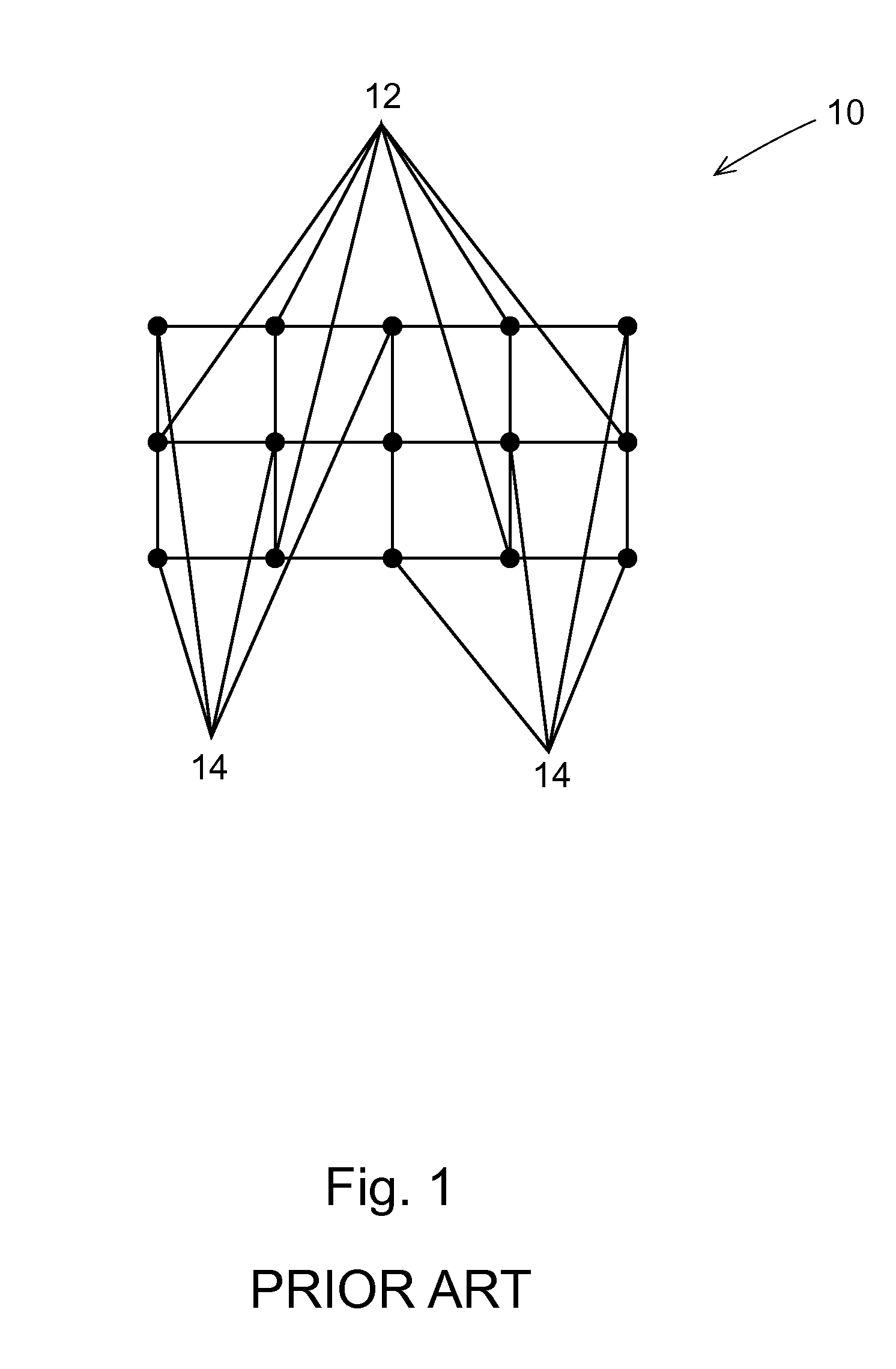
[0033]An improvement over diffuse optical imaging is a dense grid imaging array as shown in FIG. 5 and is generally indicated by numeral 15. In this situation, measurements are taken over multiple source detector distances with the sources identified by numeral 12 and detectors indicated by numeral 14. This high density array significantly improves lateral resolution and allows for volumetric localization of the functional signals. This is also known as depth profiling. These high density diffuse optical arrays involve many more source detector measurements with o...


PUM


Abstract

A high performance imaging system for diffuse optical tomography is disclosed. A dense grid utilizing sources, e.g., light emitting diodes (“LEDs”), that achieve high performance at high speed with a high dynamic range and low inter-channel crosstalk are complemented by a system of discrete, isolated receivers, e.g., avalanche photodiodes (“APDs”). The source channels have dedicated reconfigurable encoding control signals, and the detector channels have reconfigurable decoding, allowing maximum flexibility and optimal mixtures of frequency and time encoding and decoding. Each detector channel is analyzed by dedicated, isolated, high-bandwidth receiver circuitry so that no channel gain switching is necessary. The resulting improvements to DOT system performance, e.g., increased dynamic range and decreased crosstalk, enable higher density imaging arrays and provide significantly enhanced DOT image quality. A processor can be utilized to provide sophisticated three dimensional modeling as well as noise reduction.

Description

CROSS REFERENCE TO RELATED APPLICATIONS[0001]This application claims the benefit of U.S. Provisional Application No. 60 / 871,503 filed Dec. 22, 2006, which is hereby incorporated by reference in its entirety.STATEMENT REGARDING FEDERALLY SPONSORED RESEARCH & DEVELOPMENT[0002]This invention was made with government support under grants NIH:NINDS K25 NS44339 A Jul. 1, 2002-Jun. 30, 2007 awarded by the U.S, National Institutes of Health. The government has certain rights in the invention.BACKGROUND OF THE INVENTION[0003]Diffuse optical imaging (“DOI”) is an imaging methodology that can be utilized in mapping the functional activity in the human brain. With unique capabilities that include functional neuroimaging method, DOI complements and expands upon the other more established modalities such as Positron Emission Tomography (“PET”) and Magnetic Resonance Imaging (“MRI”). While tremendously useful, the scanning environments of MRI and PET brain instruments generally require a fixed hea...

Claims


Application Information

Patent Timeline
Patent Type & Authority Patents(United States)
IPC IPC(8): A61B6/00
CPCA61B5/0073A61B5/0042
Inventor CULVER, JOSEPHPERRY, GAVINZEFF, BENJAMIN
Owner WASHINGTON UNIV IN SAINT LOUIS
Why Eureka
Try Eureka