Eureka AIR delivers breakthrough ideas for toughest innovation challenges, trusted by R&D personnel around the world.

High frequency module provided with power amplifier

a technology of high frequency modules and power amplifiers, applied in waveguide type devices, cross-talk/noise/interference reduction, non-printed electric components of printed circuits, etc., can solve the problems of reduced isolation, increased heat generation, and increased noise, so as to maintain heat dissipation properties and stable operation of power amplifiers

Active Publication Date: 2011-07-12
SNAPTRACK
View PDF15 Cites 13 Cited by
  • Summary
  • Abstract
  • Description
  • Claims
  • Application Information

AI Technical Summary

Benefits of technology

[0012]It is therefore an object of the present invention to provide a small, high-performance high frequency module while maintaining heat-dissipating properties and stable operation of the power amplifier.
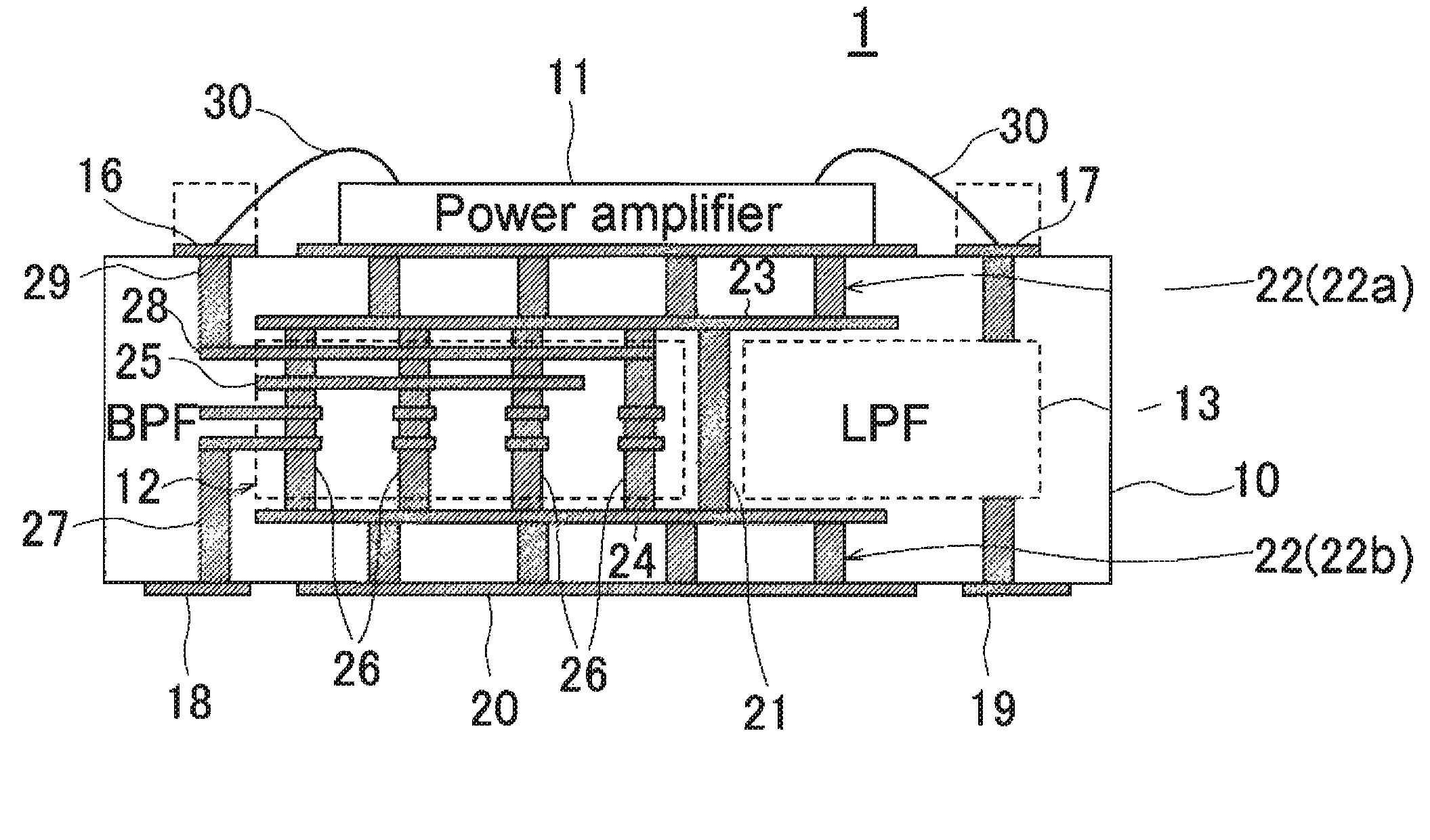
[0014]In accordance with the present invention, the first and second filters are disposed substantially directly below the power amplifier IC, and the coupling-reducing ground vias between the filters double as the thermal vias of the power amplifier IC. Accordingly, isolation is not reduced even when the first and second filters are proximately disposed. Therefore, the entire module can be reduced in size while maintaining the stability of the operation of the power amplifier and the heat-dissipating properties of the power amplifier.
[0016]In the present invention, it is preferred that the first filter be composed of a ¼ wavelength (λ / 4) resonator in which an interdigital electrode is used. In accordance with a λ / 4 wavelength resonator in which an interdigital electrode (hereinbelow simply referred to as an interdigital λ / 4 resonator) is used, a small, high-performance balance band-pass filter can be achieved, and is easily incorporated into a multilayered substrate. Since the interdigital λ / 4 resonator constituting the first filter has numerous ground vias on the structure, the total number of via holes can be reduced by using the ground vias as power amplifier thermal vias, and the high frequency module can be reduced in size. A smaller structure is facilitated and balance characteristics of a balance signal are also excellent in comparison with the case that a ½ wavelength resonator is used, or the case in which two simple ¼ wavelength resonators that are not interdigitally coupled are used, because the interdigital λ / 4 resonator has a pair of balance terminals connected to a pair of interdigitally coupled ¼ resonators. The interdigital λ / 4 resonator has ground vias and an interdigital electrode, and heat is transferred to the multilayered substrate by way of numerous electrode patterns constituting the interdigital electrode, whereby heat is dispersed. Therefore, a heat-dissipating effect by way of the interdigital electrode can be obtained.
[0019]In this manner, in accordance with the present invention, a small, high-performance high frequency module can be provided while maintaining heat-dissipating properties and stable operation of the power amplifier.

Problems solved by technology

As described above, thermal vias for dissipating heat are required because the power consumption of a power amplifier is considerable and the amount of generated heat is also considerable.
On the other hand, there is a problem in that the spacing between the first filter and second filter disposed in the pre-stage and post-stage of the power amplifier are brought closer together as the high frequency module is made smaller, the filters become electromagnetically coupled, and isolation is reduced.
When isolation between the filters is low in comparison with the gain of the power amplifier, there is a problem in that feedback is applied to the power amplifier by way of the pre- and post-filters, the operation of the power amplifier becomes unstable, and in the worst case, the power amplifier oscillates.

Method used


Image

  • High frequency module provided with power amplifier
  • High frequency module provided with power amplifier
  • High frequency module provided with power amplifier

Examples


Embodiment Construction

[0028]Preferred embodiments of the present invention will be described in detail hereinafter with reference to the accompanying drawings.

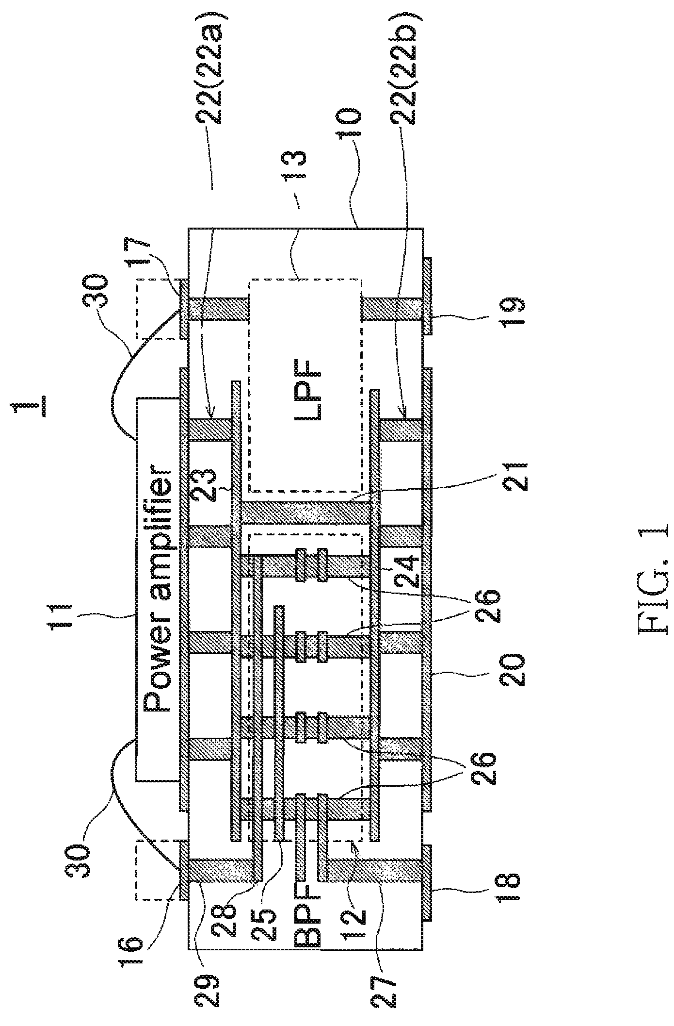
[0029]FIG. 1 is a schematic cross-sectional view showing the structure of a high frequency module of a preferred embodiment of the present invention.

[0030]As shown in FIG. 1, a high frequency module 1 is provided with a multilayered substrate 10, a power amplifier IC 11 mounted on an upper surface of the multilayered substrate 10, and first and second filters 12, 13 formed on an inner layer of the multilayered substrate 10.

[0031]The multilayered substrate 10 is a circuit substrate on which a wiring pattern is printed on a surface layer or an inner layer. It is preferred that the multilayered substrate 10 be a ceramic substrate having excellent heat and moisture resistance as well as good high frequency characteristics, and particularly preferred is an LTCC (Low Temperature Co-fired Ceramic) substrate. An LTCC can be co-fired at a low temperature of...


PUM


Abstract

The present invention is provided with a high frequency module comprising a multilayered substrate, a power amplifier IC mounted on the upper surface of the multilayered substrate, first and second filters disposed substantially directly below the power amplifier IC in an inner layer of the multilayered substrate, and coupling-reducing ground vias disposed between the first filter and the second filter. At least the first filter is disposed substantially directly below the power amplifier IC. The coupling-reducing ground vias double as thermal vias for dissipating heat generated by the power amplifier IC.

Description

TECHNICAL FIELD[0001]The present invention relates to a high frequency module that is preferably used in a mobile phone, wireless LAN, and other wireless communication devices, and particularly relates to a high frequency module provided with a power amplifier.BACKGROUND OF THE INVENTION[0002]Mobile phones, wireless LANs, and other wireless communication devices are provided with a high frequency circuit, and a power amplifier is used in the high frequency circuit. A power amplifier is a component required in a transmitting circuit of a communication device. In recent years in particular, it is expected that a wireless LAN function is mounted in a mobile phone, and there is a need for smaller-sized high frequency circuits. In view of this need, a high frequency module in which a power amplifier and a filter disposed in the pre- and post-stages are integrally formed in the high frequency circuit.[0003]FIG. 5 is a block diagram showing an example of the configuration of a high frequen...

Claims


Application Information

Patent Timeline
Patent Type & Authority Patents(United States)
IPC IPC(8): H05K1/18
CPCH04B1/03H04B1/04H05K1/0206H05K1/16H01L2224/48091H05K2201/10166H01L2924/19105H01L2224/48227H05K2201/1006H05K1/0231H05K1/0233H05K1/0243H05K1/0298H01L2924/00014
Inventor GOI, TOMOYUKIADACHI, TAKUYAAJIOKA, ATSUHIHACHIGA, HITOSHI
Owner SNAPTRACK
Why Eureka
Eureka Blog
Learn More