
Content compression in networks

a content compression and network technology, applied in the field of content compression in networks, can solve the problems of affecting performance, affecting network performance, and affecting network performance, and achieve the effects of reducing network costs, reducing network traffic, and reducing network traffi

Active Publication Date: 2011-07-05
MICROSOFT TECH LICENSING LLC
View PDF22 Cites 53 Cited by
  • Summary
  • Abstract
  • Description
  • Claims
  • Application Information

AI Technical Summary

Benefits of technology

[0004]This Summary is provided to introduce a selection of representative concepts in a simplified form that are further described below in the Detailed Description. This Summary is not intended to identify key features or essential features of the claimed subject matter, nor is it intended to be used in any way that would limit the scope of the claimed subject matter.

Problems solved by technology

However, consolidated data centers drive up networking costs and also hurt performance, because, for example, what would have normally been LAN traffic (e.g., between a local client and a local file server) becomes much slower WAN traffic (e.g., between a local client and a remote file server).
However, this increases the complexity and cost of developing and administering the services.
A similar tradeoff arises in the context of consumer services such as web-based email and on-demand video streaming targeted at a global audience; geographically distributing content improves performance, but at a high operational cost.
In sum, while consolidated data centers are beneficial with respect to cost savings in data storage and administration, there is a significant loss of performance and increase in networking costs when they are used.

Method used


Image

  • Content compression in networks
  • Content compression in networks
  • Content compression in networks

Examples


Embodiment Construction

lative content decompression.

[0020]FIG. 10 is a block diagram representing example components for implementing compression-aware routing.

[0021]FIG. 11 is a block diagram representing example components for implementing packet scheduling and fairness.

[0022]FIG. 12 is a block diagram representing example components for implementing

[0023]FIG. 13 shows an illustrative example of a computing environment into which various aspects of the present invention may be incorporated.

DETAILED DESCRIPTION

[0024]Various aspects of the technology described herein are generally directed towards content compression in networks that operates in a manner that saves bandwidth costs / improves networking performance by eliminating redundancy in traffic. To this end, there is generally described protocol-independent content compression between hosts and access routers, between routers / middleboxes on bandwidth-limited links, and also directly between hosts.

[0025]In one aspect, the technology described herein pr...


PUM


Abstract

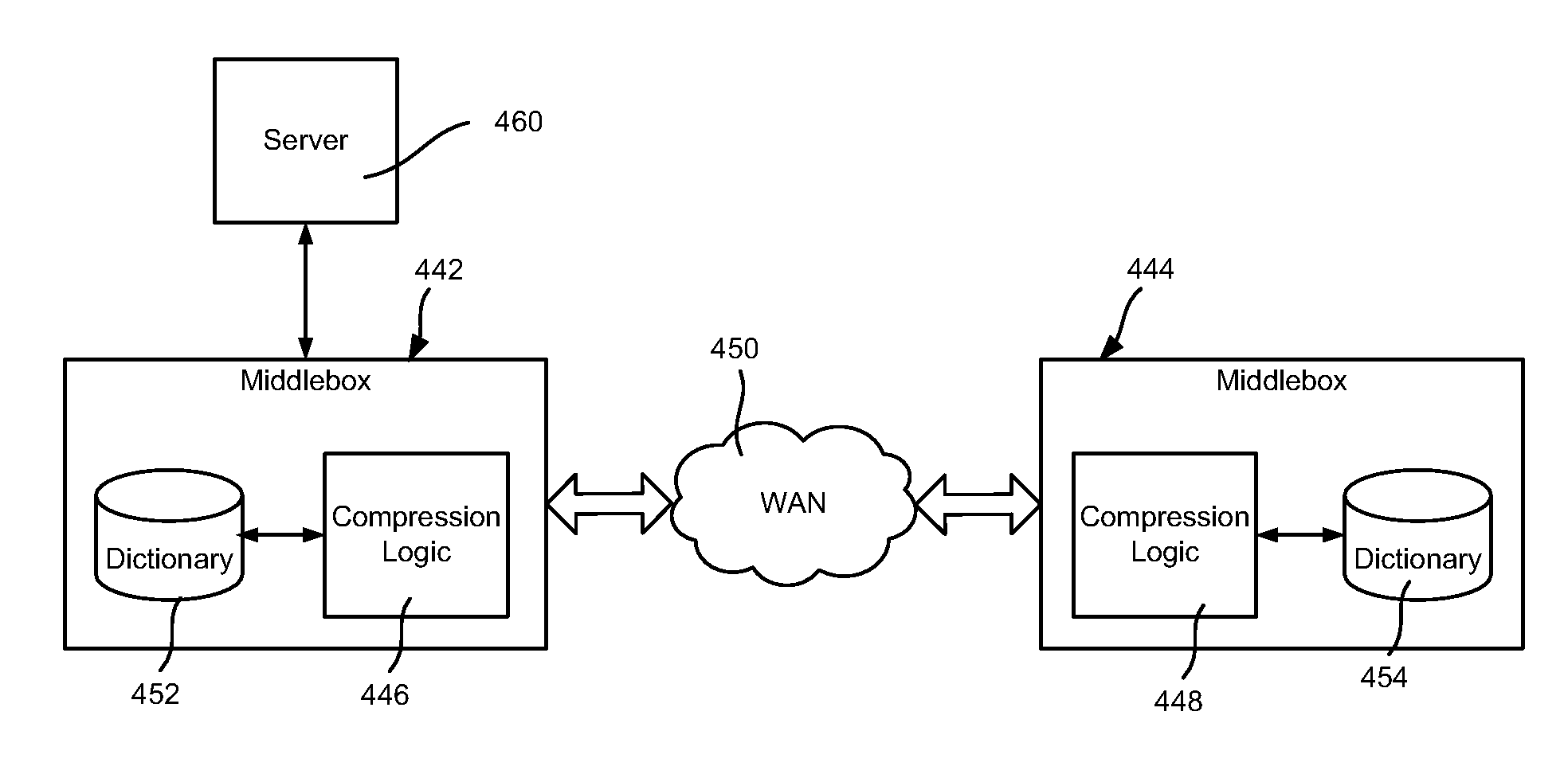
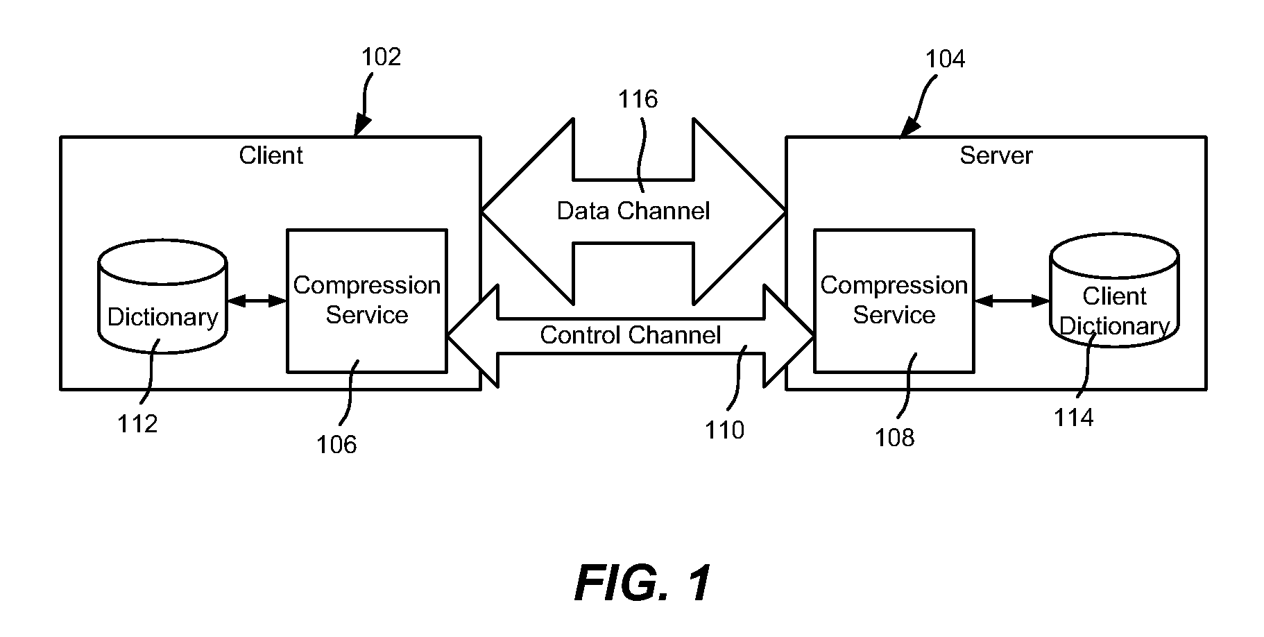
Described is transparently compressing content for network transmission, including end-to-end compression. An end host or middlebox device sender sends compressed packets to an end host or middlebox device receiver, which decompresses the packets to recover the original packet. The sender constructs compressed packets including references to information maintained at the receiver, which the receiver uses to access the information to recreate actual original packet content. The receiver may include a dictionary corresponding to the sender, e.g., synchronized with the sender's dictionary. Alternatively, in speculative compression, the sender does not maintain a dictionary, and instead sends a fingerprint (hash value) by which the receiver looks up corresponding content in its dictionary; if not found, the receiver requests actual content. Scheduling to maintain fairness and smoothing bursts to coexist with TCP congestion control are also described, as are techniques for routing compressed data over networked end hosts and / or compression-enabled middlebox devices.

Description

BACKGROUND[0001]Many networked services have global users, both in the consumer and enterprise spaces. For example, a large corporation may have branch offices at dozens of cities around the world. In such a setting, the servers that power the corporation's IT services (e.g., email servers, file servers) may be centralized / concentrated at one location or a small number of locations, sometimes referred to as consolidated data centers. This lowers administration costs. However, consolidated data centers drive up networking costs and also hurt performance, because, for example, what would have normally been LAN traffic (e.g., between a local client and a local file server) becomes much slower WAN traffic (e.g., between a local client and a remote file server).[0002]As is understood, the servers and services may be alternatively distributed so as to be closer to clients. However, this increases the complexity and cost of developing and administering the services. A similar tradeoff aris...

Claims


Application Information

Patent Timeline
Patent Type & Authority Patents(United States)
IPC IPC(8): G06F15/16G06F15/177H04L12/66H04J3/24
CPCH04L67/2828H04L67/2876H04L67/5651
Inventor RAMJEE, RAMACHANDRANBHAGWAN, RANJITAPADMANABHAN, VENKATA N.CHAWLA, MANVEER SINGH
Owner MICROSOFT TECH LICENSING LLC
Learn More