
Integral turbine blade and platform

a turbine blade and platform technology, applied in the field of fluid reaction surfaces, can solve the problems of shortened life, increased manufacturing costs, limited material properties of the first stage vanes and rotor blades, etc., and achieve the effects of reducing defective castings, improving thermal mechanical fatigue, and improving life cycle fatigu

Inactive Publication Date: 2011-07-05
FLORIDA TURBINE TECH
View PDF20 Cites 62 Cited by
  • Summary
  • Abstract
  • Description
  • Claims
  • Application Information

AI Technical Summary

Benefits of technology

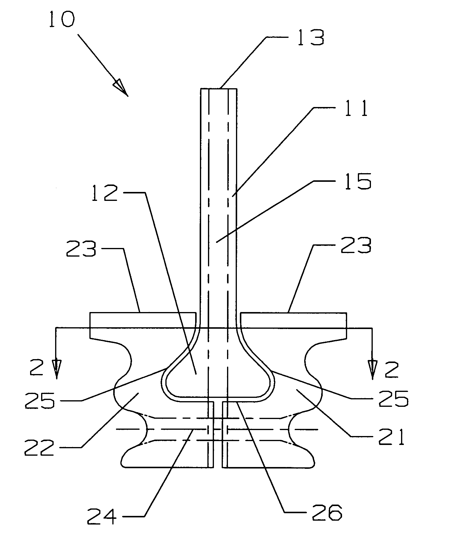
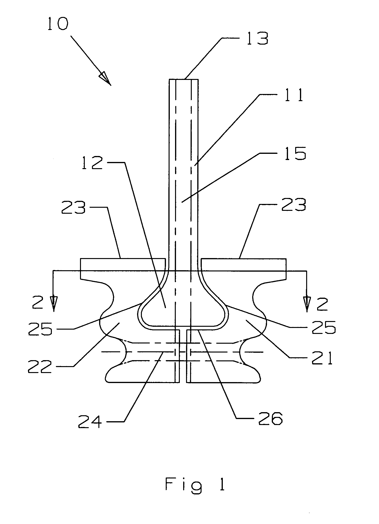
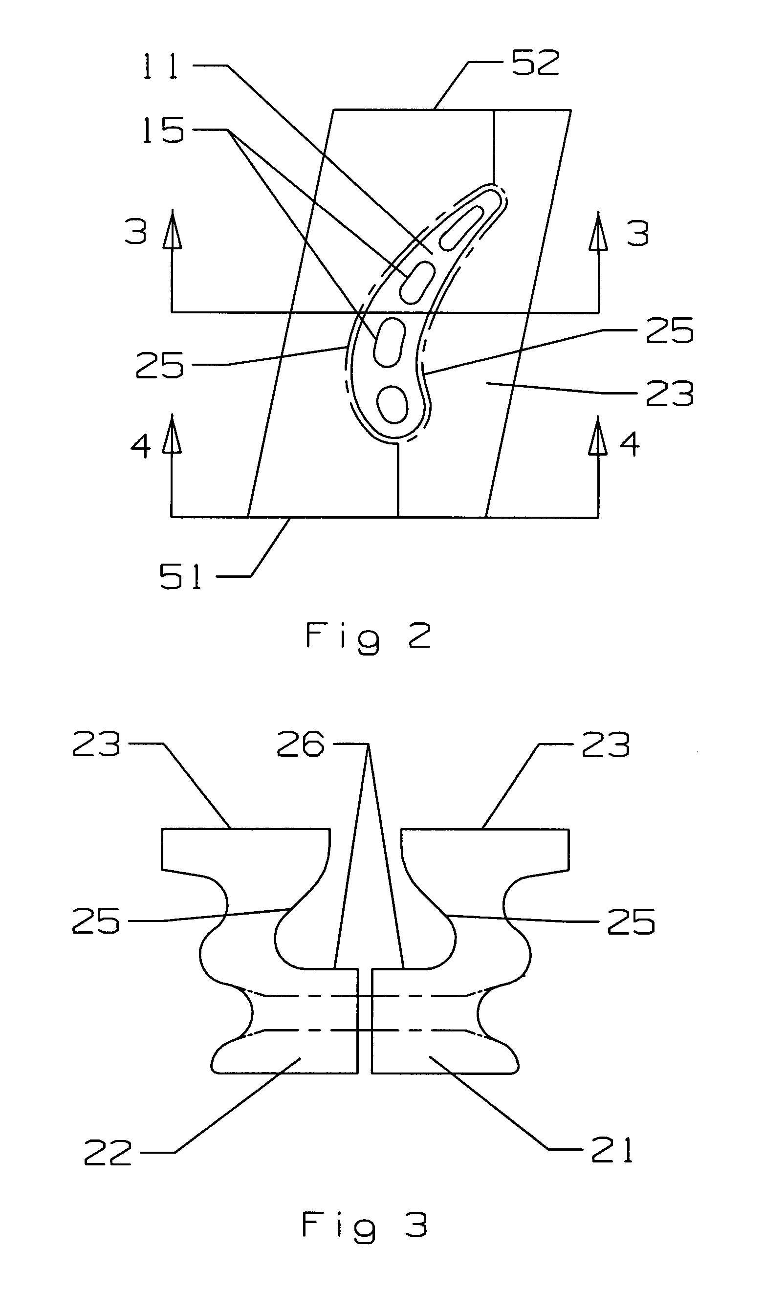
[0012]The present invention is a composite turbine blade made from an airfoil portion secured to a two piece platform portion in order that the airfoil can be formed from a single crystal material without having to form the platform from the same single crystal in order to reduce defective castings. The airfoil portion includes a root with a dovetail shaped end which fits within a dovetail shaped slot formed between the two platform halves that are secured together by a fastener to secure the airfoil portion to the platform. The platform halves include a fir-tree configuration so that the turbine blade assembly can be inserted into a slot in the rotor disk. The present invention allows for a turbine blade to be made from a single crystal material with the platform decoupled from the airfoil. This allows for the blade to have an improved life over the prior art turbine blades, improved thermal mechanical fatigue, improved life cycle fatigue and improved creep resistance.

Problems solved by technology

However, the inlet temperature is limited to the material properties of the first stage vanes and rotor blades.
However, single crystal blades that are formed with the blade platforms as a single piece have very high casting failure rates which lead to higher manufacturing costs.
The higher resulting stress on the blade can result in shortened life.

Method used


Image

  • Integral turbine blade and platform
  • Integral turbine blade and platform
  • Integral turbine blade and platform

Examples


Embodiment Construction

[0021]The present invention is a turbine blade for use in a gas turbine engine, especially for an industrial gas turbine engine. The turbine blade includes a platform separate and uncoupled from the airfoil portion so that the airfoil can be made from a single crystal material with less casting defects than would the single piece turbine blade with the platform and airfoil formed as a single piece. FIG. 1 shows a front view of a cross section of the turbine blade of the present invention. The blade includes an airfoil portion 11 with a blade tip 13 and a dovetail 12 on the root end of the blade 11. The airfoil portion 11 as seen in FIG. 2 has a curvature typical of turbine blades in which the airfoil portion includes both curvature and twist extending from the platform to the blade tip. The airfoil 11 also can include one or more cooling air passages 15 to provide cooling air for the blade. The cooling air passages 15 can be radial passages or a series of serpentine flow passages. T...


PUM


Abstract

A turbine blade for a gas turbine engine, in which the turbine blade includes an airfoil portion with a root having a dovetail shape, and two platform halves that include a dovetail shaped opening within the platform halves to secure the blade root within the platform halves when fastened together. The platform halves have an outer fir tree shaped surface so that the blade assembly can be inserted into a slot within a rotor disk. the blade is uncoupled from the platform in the invention so that the airfoil can be made from a single crystal material with low casting defects because the platform is not cast with the airfoil. the two platform halves include the openings with side walls that are curved to follow the contour of the airfoil root so that the airfoil is secured within the platform halves against all directions of movement. An annular groove extends around the platform opening to provide for a seal to produce a seal between the high pressure cooling air supply passage within the platform and the lower pressure hot gas flow passing through the blade.

Description

CROSS-REFERENCE TO RELATED APPLICATIONS[0001]This application is related to U.S. patent application Ser. No. 11 / 729,110 filed concurrently with this application and entitled TURBINE BLADE WITH SPAR AND SHELL CONSTRUCTION.BACKGROUND OF THE INVENTION[0002]1. Field of the Invention[0003]The present invention relates generally to fluid reaction surfaces, and more specifically to a turbine blade with a separately formed platform.[0004]2. Description of the Related Art including information disclosed under 37 CFR 1.97 and 1.98[0005]In a gas turbine engine, such as an aero engine used to power an aircraft or an industrial gas turbine engine used to produce electrical power, a turbine section includes a plurality of stages of rotor blades and stator vanes to extract the energy from the hot gas flow passing through. The engine efficiency can be improved by increasing the temperature of the hot gas flow entering the turbine. However, the inlet temperature is limited to the material properties...

Claims


Application Information

Patent Timeline
Patent Type & Authority Patents(United States)
IPC IPC(8): F01D5/30
CPCF01D5/025F01D5/147F01D5/3007Y02T50/672F05D2300/606Y02T50/60
Inventor DAVIES, DANIEL O.
Owner FLORIDA TURBINE TECH
Learn More