
Capacitor based energy storage

a capacitor and energy storage technology, applied in the direction of dynamo-electric converter control, apparatus with intermediate ac conversion, instruments, etc., can solve the problems of low efficiency, low efficiency, and low discharge rate of current electrically driven vehicles, so as to prolong the time the capacitor can drive the work producing device and control the capacitor discharge.

Active Publication Date: 2011-06-28
CALLOWAY RANDALL L
View PDF10 Cites 0 Cited by
  • Summary
  • Abstract
  • Description
  • Claims
  • Application Information

AI Technical Summary

Benefits of technology

[0009]Interestingly, the impedance of the transformer subjected to the alternating current acts to prevent immediate discharge of the capacitor thereby prolonging the time the capacitor can drive its work producing device. Control of the capacitor discharge can also be ensured by adding one or more capacitors in the primary transformer coil circuit.

Problems solved by technology

Although batteries have undergone several centuries of development, deficiencies remain particularly for applications which recently have become practical or desirable.
Current electrically driven vehicles are not close to being competitive, in cost or performance, with internal combustion engine driven cars and trucks.
A major problem with capacitors as energy storage devices is they discharge immediately, producing a relatively large burst of energy over a very short time.
Often, this does meet the requirements of the device to be driven, i.e. often the driven device requires delivery of energy over a prolonged period of time.
In other words, the discharge rate of capacitors is often not matched with the energy rate requirement of a device that is desired to be powered.
Another major problem with capacitors is the voltage declines as energy is discharged.
This also produces a mismatch of the characteristics of capacitors compared to the requirements of a device to be driven.
As the energy stored in a capacitor is used, the voltage declines so that electrical motors, for example, normally cannot be driven by capacitors for a prolonged length of time.

Method used


Image

  • Capacitor based energy storage
  • Capacitor based energy storage
  • Capacitor based energy storage

Examples


Embodiment Construction

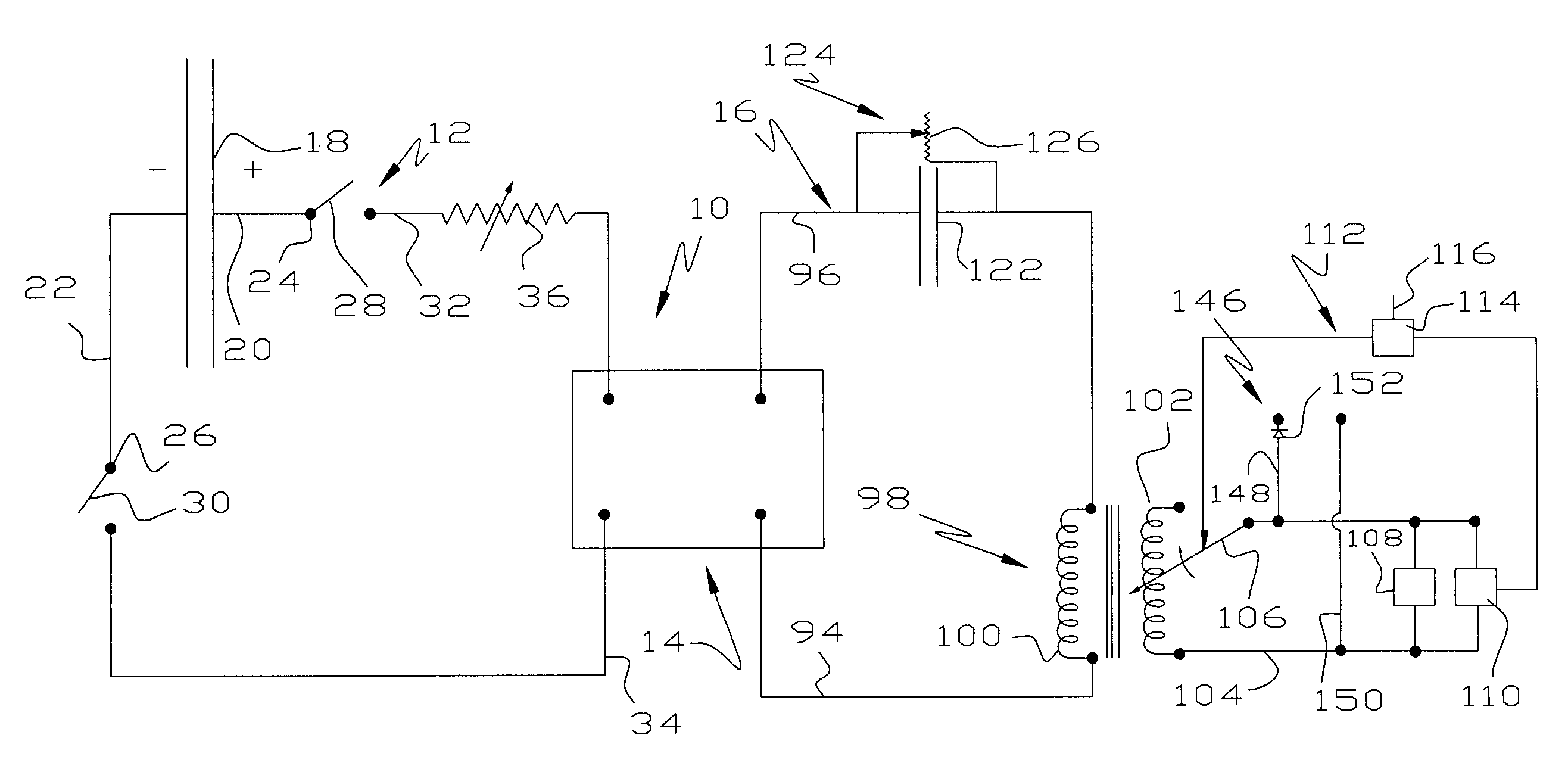
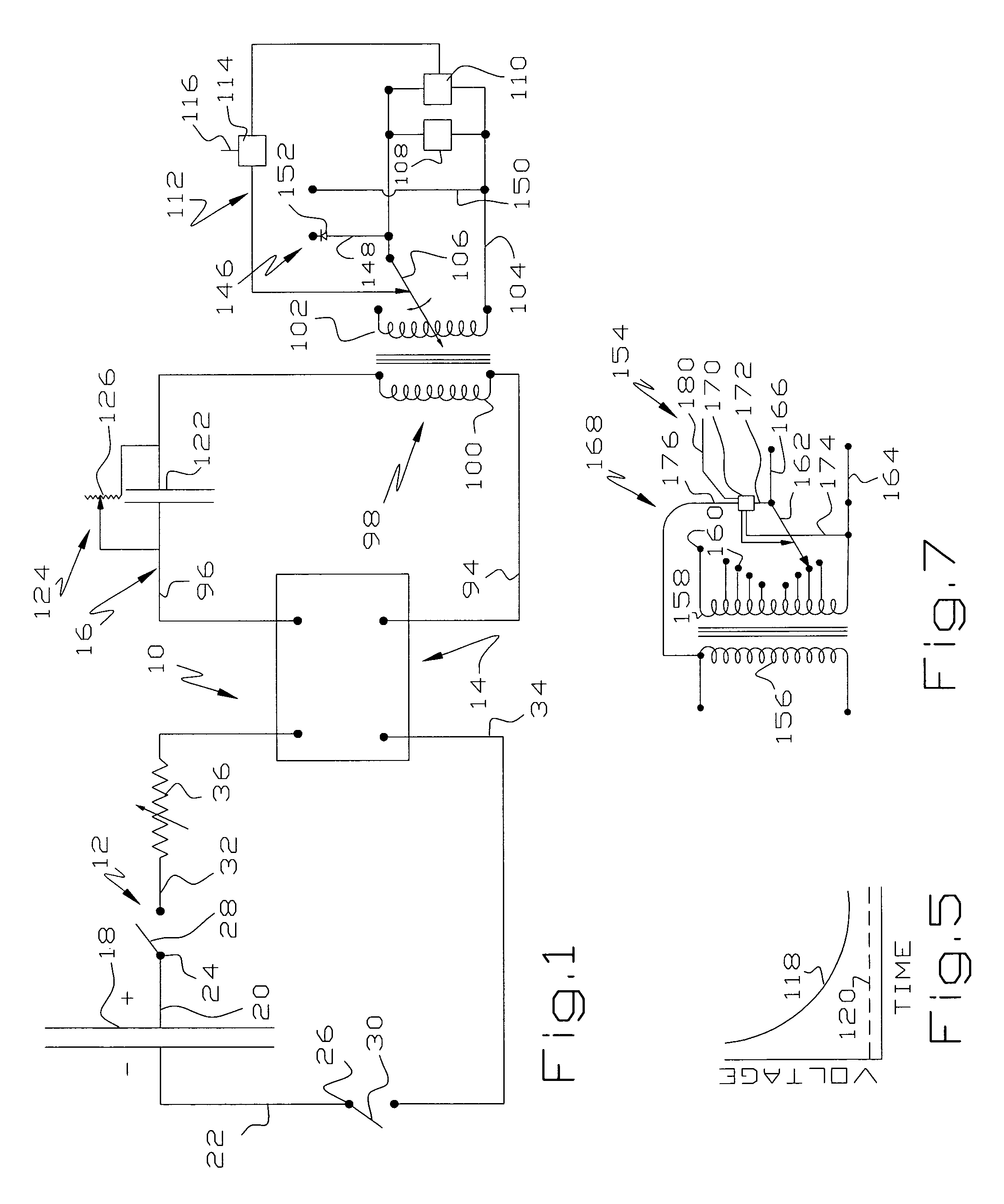
[0021]Referring to FIG. 1, an energy storage device or circuit 10 comprises, as major components, a capacitor circuit 12, an inverter 14 having an input in circuit with the circuit 12 and an output in circuit with a transformer circuit 16.

[0022]The capacitor circuit 12 comprises one or more capacitors or capacitor packs 18 of suitable size connected to leads 20, 22 which connect to a terminal 24, 26 of switches 28, 30 so the capacitor 18 may be isolated during recharging. High Farad capacitors are not currently in great demand and the capacitors available commercially are low voltage, meaning they store little power. Conversely, high voltage capacitors that are now commercially available are used to correct power factors and have low Farad design values. However, the construction of high voltage, high Farad capacitors is well within the skill of the art.

[0023]The other side of the switches 28, 30 connect to leads 32, 34 one of which provides a varistor 36 therein. The leads 32, 34 t...


PUM


Abstract

An electrical storage device comprises a capacitor or capacitor bank capable of storing significant quantities of electricity. An inverter in circuit with the capacitor converts direct energy of the capacitor into alternating current. A variable ratio transformer is in circuit with the output of the inverter to produce an alternating current output of controlled voltage. The impedance of the transformer acts to prolong discharge of the capacitor over a significant time period. To further control the rate of discharge of the energy storage capacitor, an additional capacitor may be provided in the transformer circuit.

Description

[0001]This application is based on Provisional Application Ser. No. 61 / 000,122, filed Oct. 24, 2007, the priority of which is claimed.[0002]This invention relates to an energy storage device incorporating a capacitor and a circuit allowing slow discharge of the capacitor.BACKGROUND OF THE INVENTION[0003]The standard approach to store electrical energy is by using electrochemical batteries. Although batteries have undergone several centuries of development, deficiencies remain particularly for applications which recently have become practical or desirable. For example, the general consensus is that a practical, inexpensive electrically driven automobile awaits the development higher capacity, less expensive batteries which can be charged sufficiently to provide a practical radius of operation. Current electrically driven vehicles are not close to being competitive, in cost or performance, with internal combustion engine driven cars and trucks. Although electrically driven vehicles ha...

Claims


Application Information

Patent Timeline
Patent Type & Authority Patents(United States)
IPC IPC(8): H02P25/30
CPCB60L11/005H02J7/345B60L15/12B60L2240/70B60L2200/22Y02T10/7291Y02T90/16Y02T10/7022B60L50/40Y02T10/64Y02T10/70Y02T10/72
Inventor CALLOWAY, RANDALL L.
Owner CALLOWAY RANDALL L
Learn More