
Methods for obtaining MRI frequency maps

a frequency map and frequency technology, applied in the field of methods for obtaining mri frequency maps, can solve the problems of difficult shiming of certain objects,

Active Publication Date: 2011-06-21
THE GENERAL HOSPITAL CORP
View PDF8 Cites 16 Cited by
  • Summary
  • Abstract
  • Description
  • Claims
  • Application Information

AI Technical Summary

Benefits of technology

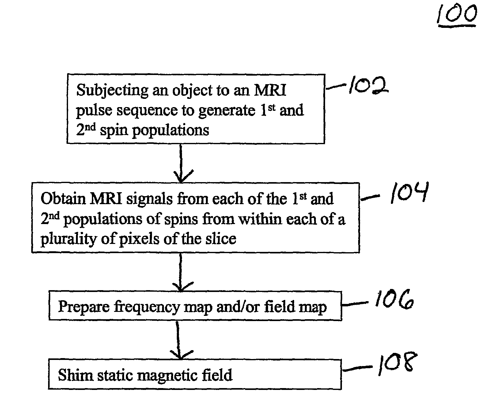
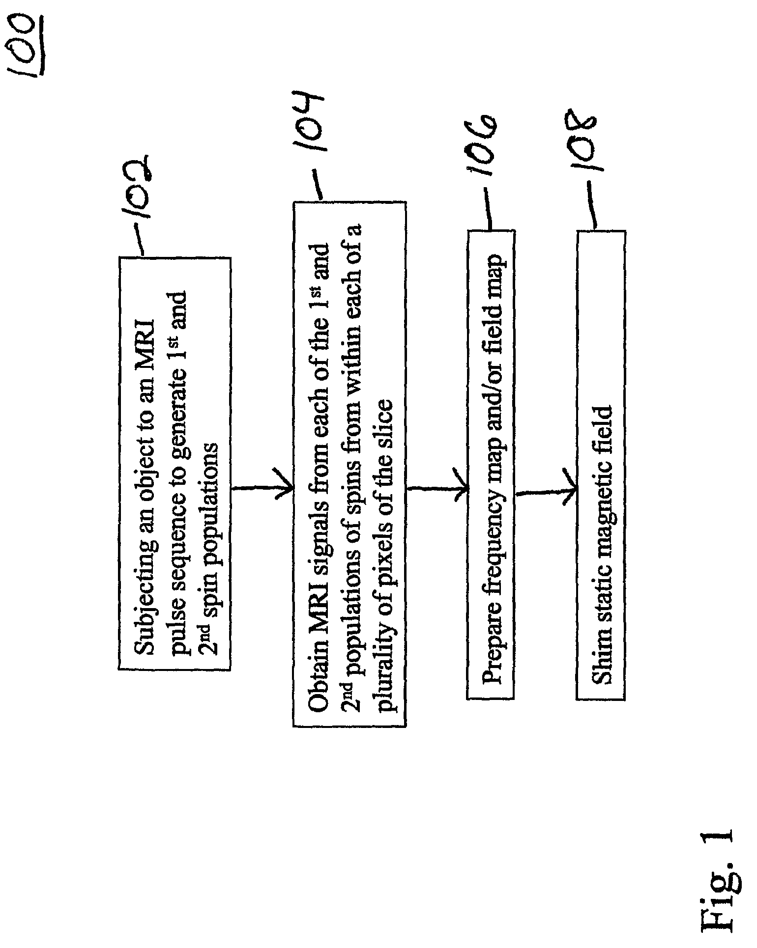
The present invention relates to MRI methods that involve obtaining MRI signals from an object using a single MRI pulse sequence. The MRI signals can be obtained by subjecting the object to a first and second radio frequency (RF) excitation pulse, and a dephasing gradient. The MRI signals can be used to determine the precessional frequency of MRI active nuclei present within different pixels of the object. The methods can be used to generate field maps that can be used to correct for variations in the field experienced by different pixels of the object. The methods can provide accurate frequency maps with reduced errors caused by position changes and movement of the object.

Problems solved by technology

Certain objects can be challenging to shim.
For example, objects that move, e.g., the heart, thorax, and abdomen, may change position within the field of the imager and are thus difficult to shim, because they may not return to exactly the same position between movements, e.g., between heartbeats or inhalations.

Method used


Image

  • Methods for obtaining MRI frequency maps
  • Methods for obtaining MRI frequency maps
  • Methods for obtaining MRI frequency maps

Examples


example 1

Obtaining MRI Signals

[0065]A General Electric 1.5T Signa MR scanner (LX, 8.2.5) with a custom 12×20 cm flexible linear surface coil was used to generate pulse sequence and obtain the MRI signals from a living subject's heart. Pulse sequences were generated and MRI signals obtained during each of 8 different cardiac cycles.

[0066]Referring to FIG. 4, each pulse sequence was a gradient echo MRI pulse sequence 400. Each pulse sequence 400 included first and second RF excitation pulses 2021, 2022, a dephasing gradient 204 and a prephasing gradient 208. A rephasing pulse was not used. Each excitation pulse 2021, 2022 was a 45° pulse. Each pulse sequence 400 excited the same slice twice during a single shot.

[0067]Pulse sequence 400 also included a plurality of readout gradients 210i. During the ith readout gradient, a subset 212i of MRI signals was acquired. The ith subset of MRI signals included a respective MRI signal corresponding to each of the RF excitation pulses 2021, 2022. Each MRI...

example 2

Preparing Frequency Maps

[0072]Frequency maps prepared from the set 212′ of MRI signals are shown in FIGS. 5a-5h. The average of these frequency maps is shown in FIG. 6. The frequency maps are nearly identical even though the frequency maps were obtained during different breath holds and between different heartbeats so that the heart was not in exactly the same position for each acquisition.

[0073]The frequency maps of FIGS. 5a-5h were acquired in the presence of a velocity encoding gradient. However, the velocity encoding gradient is not required for obtaining the frequency maps. The velocity encode affects only the phase change in the axis of velocity encoding (i.e. the change in phase with distance). When the same pixel of each of two images is compared to determine the frequency, the velocity encode cancels out.

[0074]The frequency maps of FIGS. 5a-5h were used for cardiac shimming. Referring to FIG. 7, an MR image of the heart, shimmed using the frequency map data discussed above ...


PUM


Abstract

A magnetic resonance imaging (MRI) method includes generating first and second spin populations within each of a plurality of pixels of a slice of an object. These spin populations have different phase histories. For each pixel, MRI signals from those spin populations are acquired at different times These MRI signals can then be used to determine a field strength difference between different pixels of the slice.

Description

CROSS-REFERENCE TO RELATED APPLICATIONS[0001]This application is a national phase application under 35 U.S.C. §371 of PCT International Application No. PCT / US2005 / 017212, filed May 16, 2005, which claims the benefit of U.S. Provisional Patent Application Ser. No. 60 / 570,830, filed May 14, 2004. The contents of these prior applications are incorporated by reference in their entirety.FIELD OF THE INVENTION[0002]The present invention relates to methods for obtaining MRI frequency maps.BACKGROUND OF THE INVENTION[0003]Magnetic resonance (MR) imagers are used to obtain images of objects by a process known as magnetic resonance imaging (MRI). Images of an object typically include a plurality of two-dimensional (2D) image sections (slices). Each slice includes a plurality of pixels, at different locations within the slice.[0004]The acquisition of magnetic resonance images from an object, e.g., a heart, brain, or breast, generally includes subjecting the object to a static magnetic field. W...

Claims


Application Information

Patent Timeline
Patent Type & Authority Patents(United States)
IPC IPC(8): G06K9/00G01R33/387G01R33/54G01V3/00
CPCG01R33/54G01R33/387
Inventor REESE, TIMOTHY G.WEDEEN, VAN J.
Owner THE GENERAL HOSPITAL CORP
Learn More