
Etching method for semiconductor element

a technology of etching method and semiconductor element, which is applied in the direction of semiconductor/solid-state device manufacturing, basic electric elements, electric devices, etc., can solve the problems of affecting the pattern resolution, affecting the reliability of the etching process, and affecting the to-be-formed structure, so as to ensure the completeness of the semiconductor structure, increase the reliability of the etching process, and improve the effect of pattern resolution

Active Publication Date: 2011-05-31
MACRONIX INT CO LTD
View PDF5 Cites 0 Cited by
  • Summary
  • Abstract
  • Description
  • Claims
  • Application Information

AI Technical Summary

Benefits of technology

This method enhances the reliability and completeness of semiconductor structures by maintaining pattern precision and preventing structural damage, without the need for process upgrades or new equipment, while ensuring high aspect ratio etching resolution and accuracy.

Problems solved by technology

Facing the trend of concentrating and reducing semiconductor elements, the photolithography and etching process for manufacturing semiconductor element is encountering huge challenges.
The insulating portion 14 shielded underneath will be exposed and etched by ions, and the to-be-formed structure will be damaged.
However, photo resist will collapse as photo resist thickness is too high.
Besides, during the process of exposing the photo resist layer by deep ultra violet light (DUV light) for instance, the substrate under the photo resist layer reflects the deep ultra violet light, such that part of the preserved photo resist layer is undercut and the resolution of exposure is affected.

Method used


Image

  • Etching method for semiconductor element
  • Etching method for semiconductor element
  • Etching method for semiconductor element

Examples


Embodiment Construction

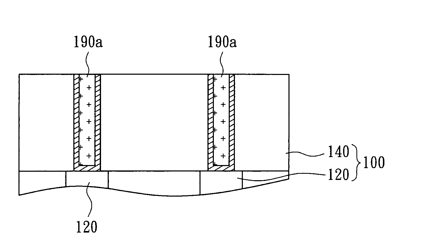
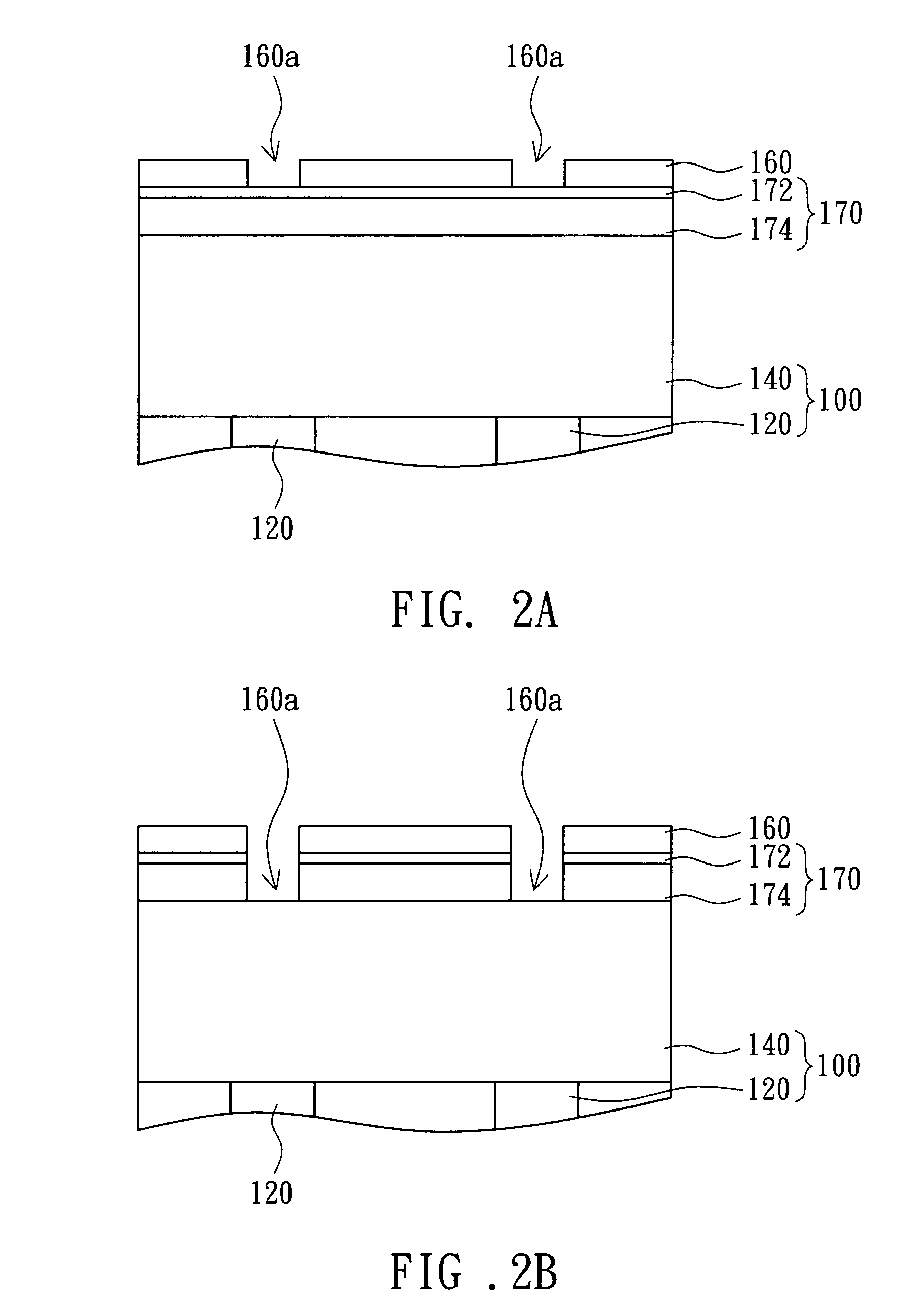
[0015]The embodiment of the invention of forming a contact hole of the manufacturing process of semiconductor element is disclosed below. Referring to FIGS. 2A-2F, cross-sectional views of the process of manufacturing a semiconductor element according to the invention are shown. Also referring to FIG. 3, a step flowchart of the method of manufacturing a semiconductor element according to the invention is shown. First, proceed to step 301 and refer to FIG. 2A, a to-be-etched substrate 100 including an insulating portion 140 and a conductive portion 120 is provided, wherein the insulating portion 140 is positioned on the conductive portion 140, the insulating portion 140 is made from silicon oxide (SixOy) for instance, and examples of the conductive portion 120 include an ion-doped source or drain. Next, proceed to step 302, a silicon-rich silicon oxide (SRO) layer 174 is formed on the to-be-etched substrate 100. Then, proceed to step 303, an anti-reflective layer 172 is formed on the...


PUM


Abstract

An etching method for semiconductor element is provided. The etching method includes the following procedure. First, a to-be-etched substrate is provided. Then, a silicon-rich silicon oxide (SRO) layer is formed on the to-be-etched substrate. Afterwards, an anti-reflective layer is formed on the SRO layer. Then, a patterned photo resist layer is formed on the anti-reflective layer. Afterwards, the anti-reflective layer, the SRO layer and the to-be-etched substrate is etched so as to form an opening.

Description

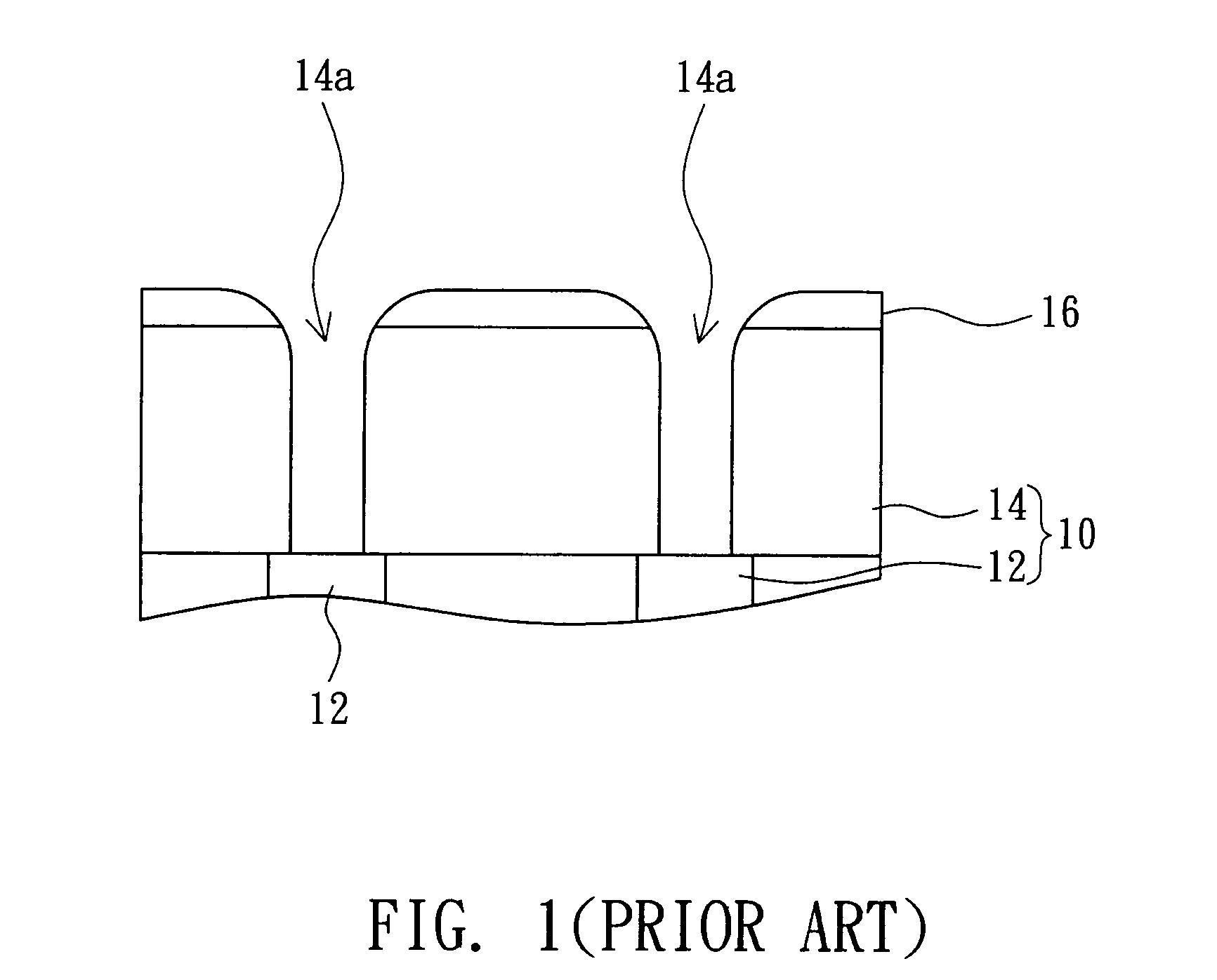
BACKGROUND OF THE INVENTION[0001]1. Field of the Invention[0002]The invention relates in general to an etching method for semiconductor element, and more particularly to an etching method for semiconductor element using an anti-reflective layer and a hard mask.[0003]2. Description of the Related Art[0004]As the technology of manufacturing semiconductor device continues to shrink, the size of electronic elements continues to be reduced and element density continues to increase. Facing the trend of concentrating and reducing semiconductor elements, the photolithography and etching process for manufacturing semiconductor element is encountering huge challenges.[0005]Take the contact hole manufacturing process of semiconductor element for example. Referring to FIG. 1, a cross-sectional view of conventionally forming a contact hole of a semiconductor element is shown. The substrate 10 includes an insulating portion 14 and a conductive portion 12. The insulating portion 14 is disposed on ...

Claims


Application Information

Patent Timeline
Patent Type & Authority Patents(United States)
IPC IPC(8): H01L21/4763
CPCH01L21/76802H01L21/31144
Inventor LUOH, TUUNGYANG, LING-WUUCHEN, KUANG-CHAO
Owner MACRONIX INT CO LTD
Learn More