
Linear motion guide unit with inside seal

a technology of motion guide unit and inside seal, which is applied in the direction of linear bearings, shafts and bearings, bearings, etc., can solve the problems of inability to meet the current demand for compact linear guide systems, unsuitable for prolonged operation, etc., and achieves the effect of convenient mounting and low production cos

Active Publication Date: 2011-05-31
NIPPON THOMPSON
View PDF8 Cites 12 Cited by
  • Summary
  • Abstract
  • Description
  • Claims
  • Application Information

AI Technical Summary

Benefits of technology

The solution effectively prevents foreign materials from entering the load-carrying races, ensuring prolonged service life and smooth operation in severe environments, while being cost-effective and compact in design.

Problems solved by technology

Even with any invasion of outside foreign materials into the slider, the most significant issue is how to protect at least the circulating circuit including the load-carrying races to allow the rolling elements running through there against the foreign materials or contaminants.
However, the inner seals in the prior linear guide system as stated earlier, because of constructed to double as the ball retainer, is insufficient in sealing performance and therefore unfit for prolonged operation under the service severity as stated above.
Moreover, the ball retainer with inner seals by itself would get larger in height in section and therefore couldn't fit the current demand to make the linear guide system compact or slim in construction.
Nevertheless, it still remains a major challenge to develop the linear motion guide units with an inside seal installed within the slider, in which the inside seal is ensured in precious position control of sealing locations, smooth sliding contact of lip-type seals with the top surface of the guide rail, and in protection of the load-carrying races against foreign materials or contaminants that would otherwise creep between the top surface of the guide rail and the carriage and / or end caps of the slider, thereby keeping the load-carrying races free of foreign materials or contaminants.

Method used


Image

  • Linear motion guide unit with inside seal
  • Linear motion guide unit with inside seal
  • Linear motion guide unit with inside seal

Examples


Embodiment Construction

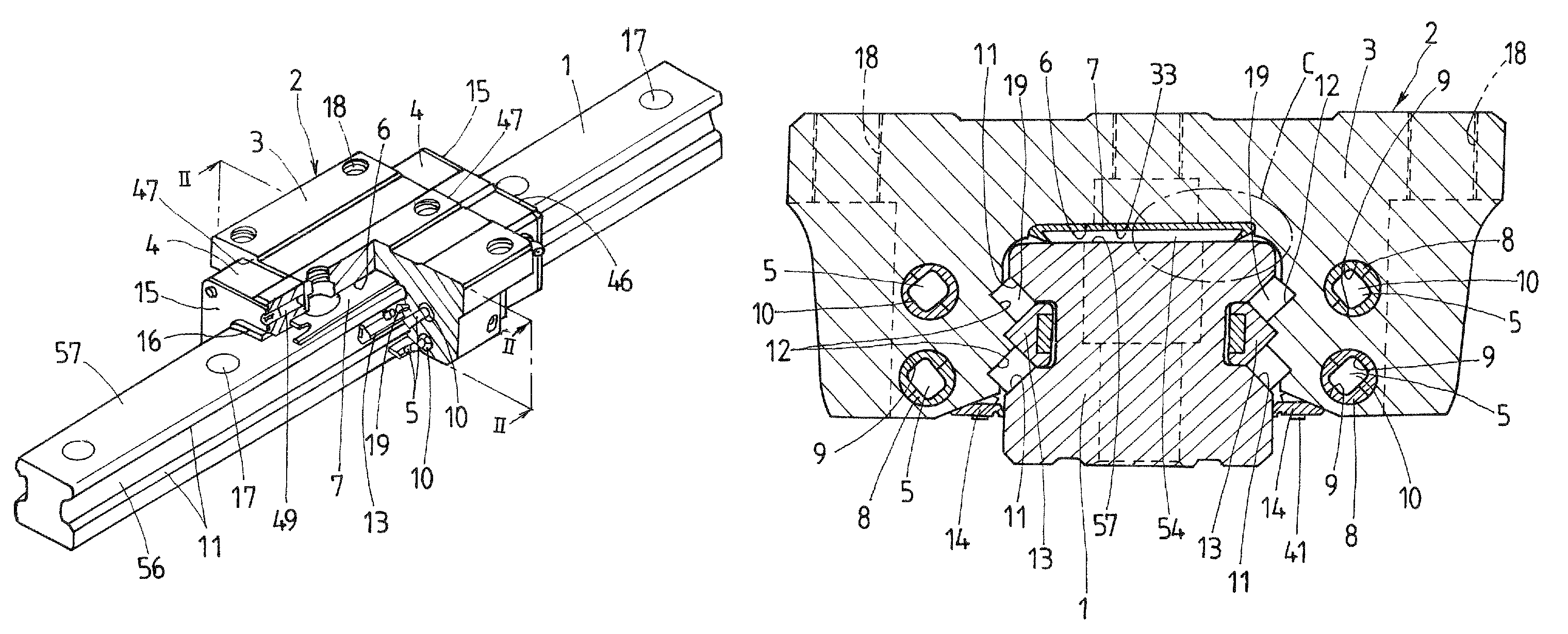
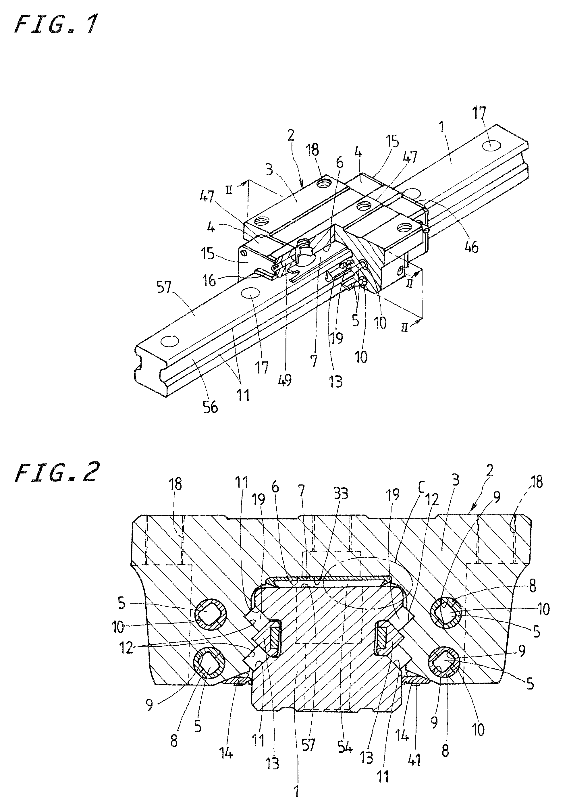
[0036]The linear motion guide unit constructed according to the present invention is best adapted for use in machinery as diverse as machine tools including cutting machines, grinding machines and woodcutting machines, and other industrial machines, which are needed to operate in worse working environment because of the occurrence of much foreign materials including dust, chips, cutting debris, and so on, or the presence of splashed fluids of cutting fluids, coolants, and so on. In the worse working conditions as stated earlier, the load-carrying races defined between a guide rail and a slider moving on the guide rail must be especially kept free of all possible foreign materials or contaminants, even when they could creep into the interior of the slider along the guide rail.

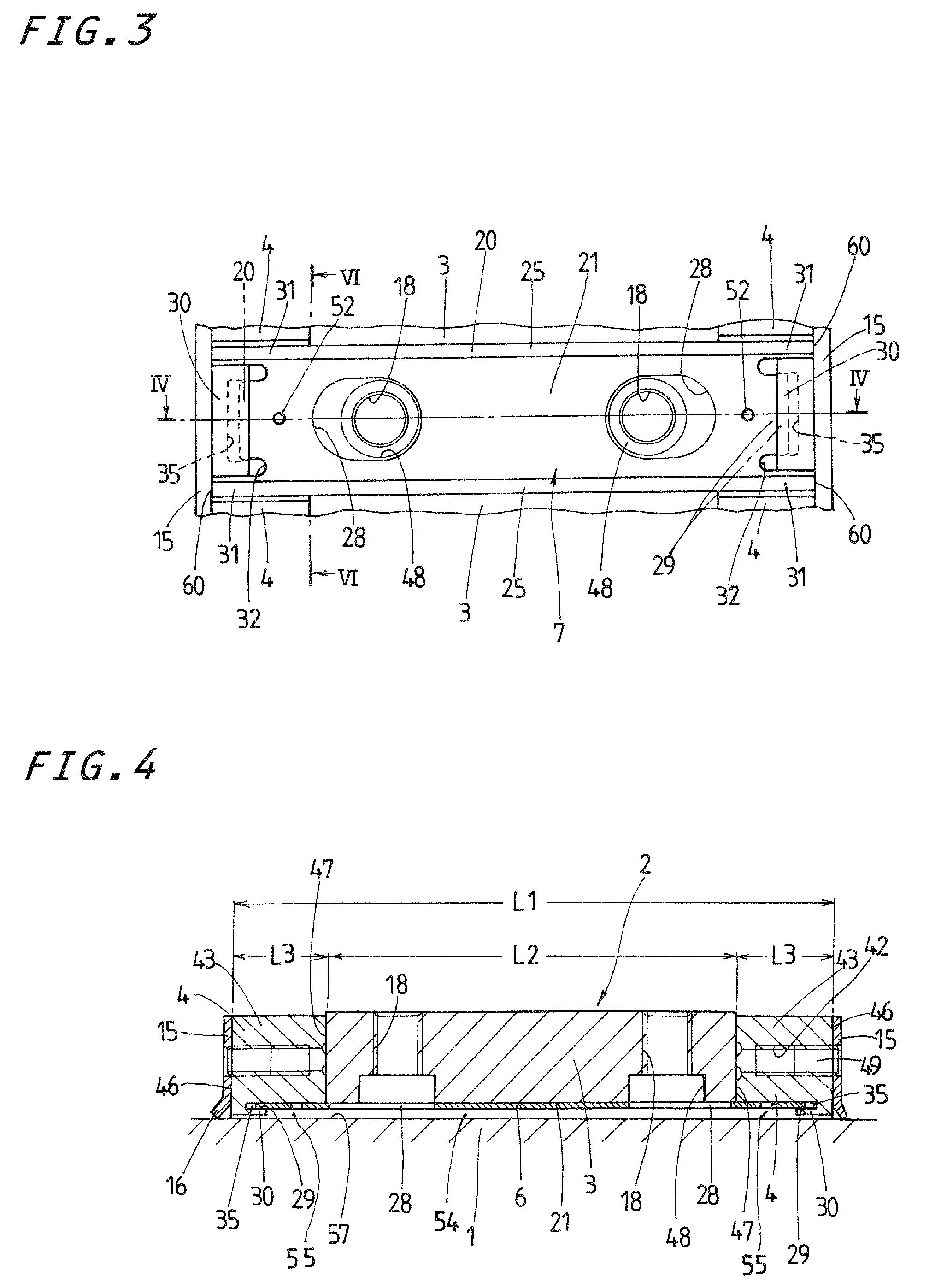
[0037]Referring now in detail to the drawings, the linear motion guide unit according to the present invention will be explained below. With the linear motion guide unit, an inside seal 7 installed deep into a r...


PUM


Abstract

An inside seal is installed in a recess open downward in the slider to keep load-carrying races kept free of foreign materials that have already crept into the inside of the slider. The inside seal is composed of a metallic core and a sealing member that includes a joint portion secured to the core and a major portion integral with the joint portion. The joint portion has a mating surface to come into engagement with a downward surface deep inside the recess cut in a carriage while the major portion includes a first lip to come into sliding engagement with a guide rail, a second lip come into abutment against an inward sidewall of the recess, and third lip to come into abutment against the downward surface.

Description

FIELD OF THE INVENTION[0001]The present invention relates to a linear motion guide system befitted to machinery including machine tools, industrial machines, and so on, which are needed to operate in severe working environment where much foreign materials including chips, debris, dirt, dusts, and so on occurs or any liquid including processing fluids, coolants, and so on splashes. More particularly, it relates to a linear motion guide system with an inside sealing unit to keep load-carrying races free of any foreign material creeping into a slider that fits over or conform to a guide rail for relatively sliding movement.BACKGROUND OF THE INVENTION[0002]As applications of the linear motion guide units grow in recent years to include the machinery working in increased operating severity, modern linear motion guide units increasingly need to work over a prolonged service life even under harshest atmosphere in which much foreign material including chips, debris, dirt, dusts, and so on o...

Claims


Application Information

Patent Timeline
Patent Type & Authority Patents(United States)
IPC IPC(8): F16C33/72F16C29/06
CPCF16C29/088F16C29/065F16C29/086
Inventor KONDO, MASATOSHI
Owner NIPPON THOMPSON
Learn More