
Apparatus for production of hydrogen gas using wind and wave action

a technology of apparatus and hydrogen gas, applied in the direction of positive displacement liquid engine, electric generator control, greenhouse gas reduction, etc., can solve the problems of lack of scalability of current hydrogen generating system, inability to provide the large amount of electricity that is becoming necessary, and inability to easily configur

Inactive Publication Date: 2011-05-24
BURTCH JOHN CHRISTOPHER
View PDF77 Cites 52 Cited by
  • Summary
  • Abstract
  • Description
  • Claims
  • Application Information

AI Technical Summary

Benefits of technology

"The present invention is a platform apparatus for producing hydrogen gas from water on a body of water. It includes a buoyant base and a support member with a wind turbine and a generator for converting wind energy into electrical energy. The electrical energy is used to power an electrolysis apparatus with carbon electrodes and a gas collection apparatus for collecting the hydrogen gas. The invention also includes a pumping apparatus for using wave motion to pump water into the electrolysis apparatus. Additionally, the invention is a scalable array of interconnected platforms that can move independently for pumping, but stay together as a whole."

Problems solved by technology

Current electricity sources are incapable of supplying the large amounts of electricity that are becoming necessary for new uses, such as for generating hydrogen gas necessary to power fuel cell automobiles.
Current hydrogen generating systems also suffer from a lack of scalability, and are not easily configured to meet varying demand for hydrogen gas production.
Furthermore, water must often be pumped to fixed locations for producing hydrogen gas using electrolysis, which is costly and expensive.

Method used


Image

  • Apparatus for production of hydrogen gas using wind and wave action
  • Apparatus for production of hydrogen gas using wind and wave action
  • Apparatus for production of hydrogen gas using wind and wave action

Examples


Embodiment Construction

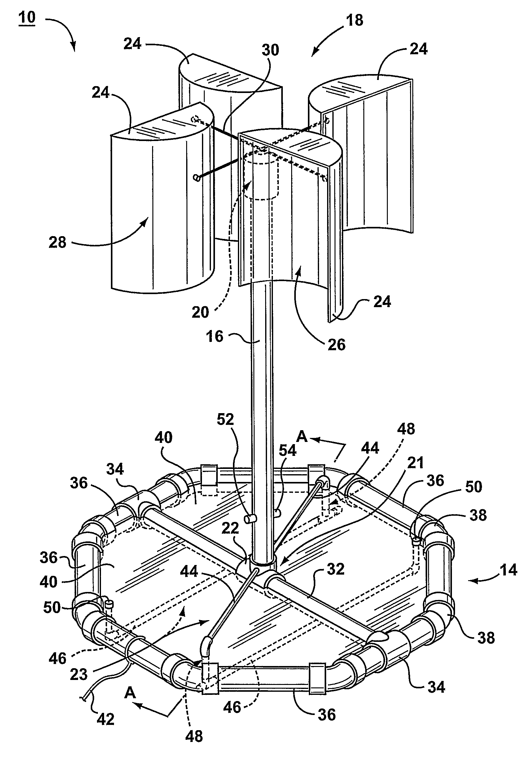
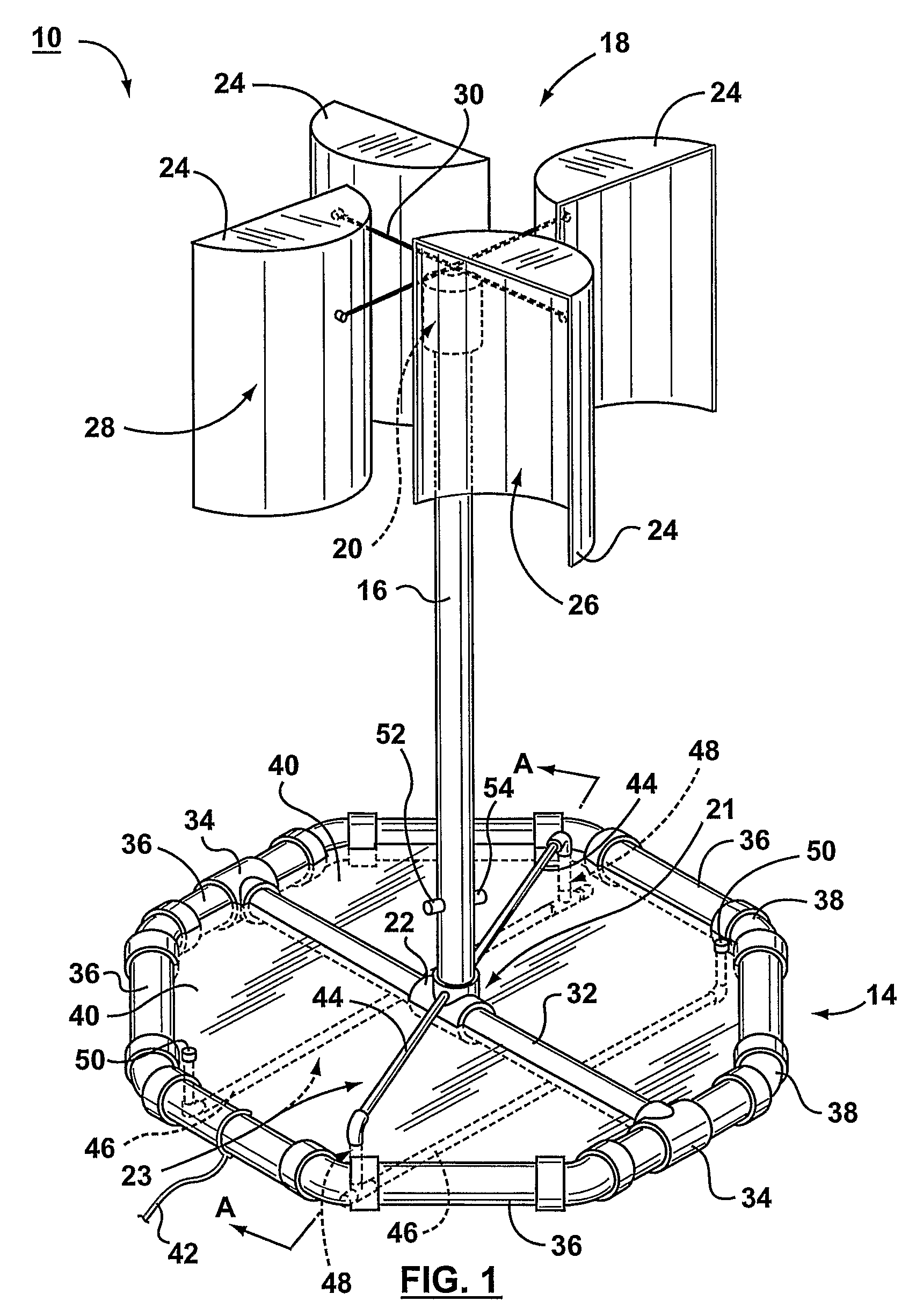
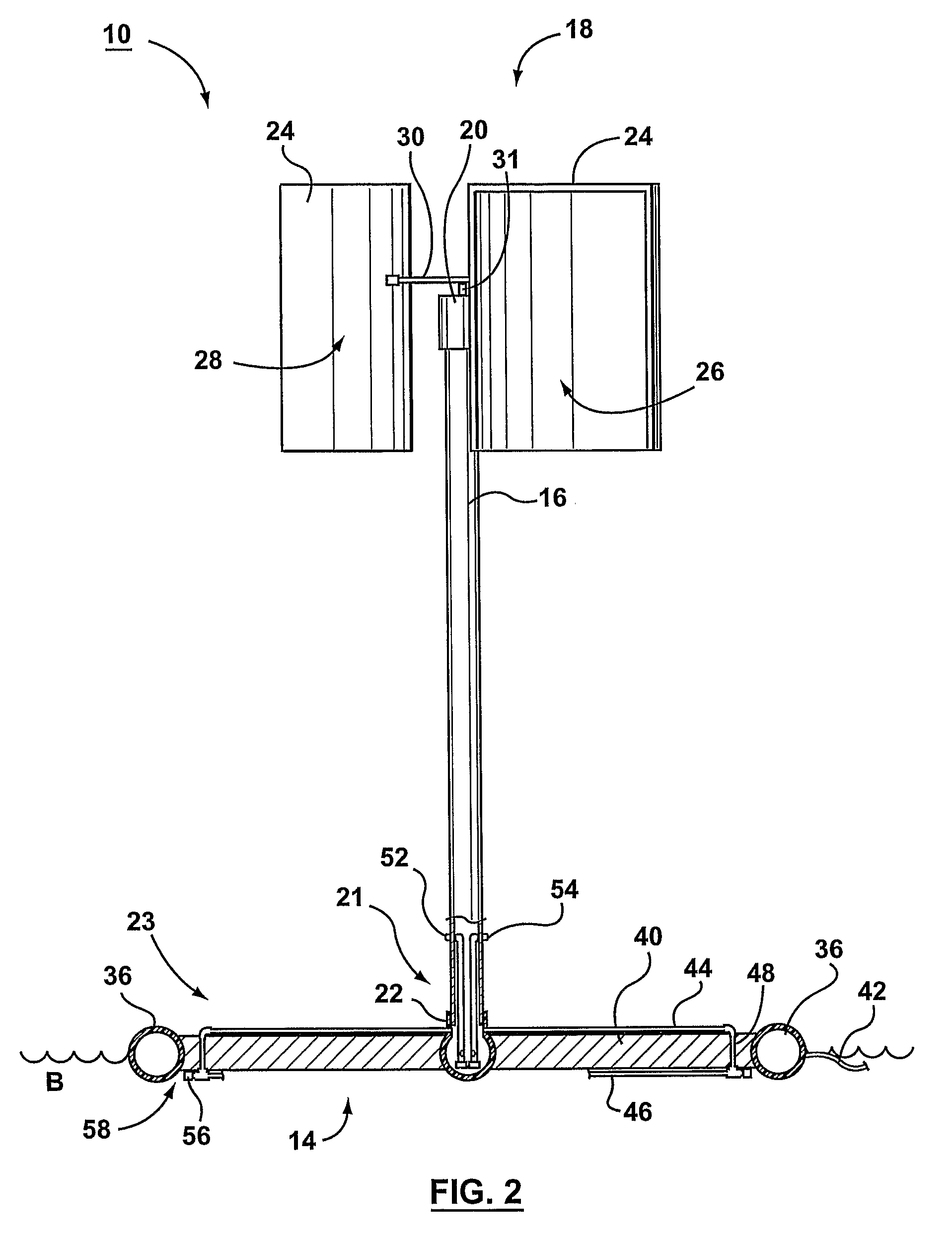
[0018]Referring to FIGS. 1, 2 and 3, illustrated therein is a platform apparatus 10 for producing hydrogen gas in accordance with a preferred embodiment of the invention. The apparatus 10 comprises a buoyant base 14 configured for floating on a body of water B such as an ocean, a support member 16 extending vertically from the base 14, a wind turbine 18 rotationally coupled to the vertical support member 16 for transforming the kinetic energy of wind into rotational energy, and a generator 20 coupled to the wind turbine 18 for transforming rotational energy generated by the wind turbine 18 into direct current (DC) electrical energy. This DC electricity is used to power an electrolysis apparatus shown generally as 21. The electrolysis apparatus 21 uses the electricity produced by the generator 20 to create hydrogen gas from water collected from the body of water B.

[0019]The apparatus 10 preferably further comprises a pumping apparatus shown generally as 23 that uses the wave motion o...


PUM


Abstract

A platform apparatus for producing hydrogen gas from water includes a buoyant base configured for floating in a body of water, such as on the ocean, a vertical support member extending upwardly from the base, a wind turbine rotatably coupled to the support member for transforming the kinetic energy of wind into rotational energy, a generator coupled to the wind turbine for transforming the rotational energy generated into DC electricity, and an electrolysis apparatus affixed to the platform for using the electricity to extract hydrogen gas from water by the process of hydrolysis. The electrolysis apparatus preferably comprises an exchange chamber for storing water collected from the body of water, a pair of corrosion resistant electrodes, and a gas collection apparatus for collecting the hydrogen gas produced by electrolysis. The platform apparatus preferably includes a pumping apparatus powered by wave motion of the body of water for supplying water to the electrolysis apparatus. A gearing system preferably allows the generator to be driven at a greater rotational speed than the wind turbine.

Description

FIELD OF THE INVENTION[0001]The present invention relates to apparatus for producing hydrogen gas, and in particular to apparatus for producing hydrogen gas through electrolysis of water.BACKGROUND OF THE INVENTION[0002]The process of extracting Hydrogen gas from water by electrolysis has been known since at least the 1800's. Many of the technological advancements that have occurred since then center around how the electricity necessary for electrolysis is produced. Originally, batteries were used as the primary source of the direct current (DC) electricity necessary for electrolysis. Currently, however, most electricity comes from power sources such as hydro dams, coal, and nuclear plants and most recently from wind and solar power. These modern electricity sources typically generate alternating current (AC) electricity, which must be converted into DC electricity for use in electrolysis through rectification.[0003]Current electricity sources are incapable of supplying the large am...

Claims


Application Information

Patent Timeline
Patent Type & Authority Patents(United States)
IPC IPC(8): F03D9/00H02P9/04F03B13/12F03B13/00F03B13/10
CPCC25B1/04F03B13/1815F03D9/008F04B17/00E02B2017/0091F05B2220/61Y02E70/10F05B2240/93F05B2240/95Y02E10/38Y02E10/725Y02E60/366F05B2240/216F03D13/25Y02E10/727F03D9/19F03D15/20F03D9/25Y02E10/30Y02E10/72Y02E60/36Y02P80/10Y02E70/30
Inventor BURTCH, JOHN CHRISTOPHER
Owner BURTCH JOHN CHRISTOPHER
Learn More