
Machine and process for personal, side mounted biomechanically engineered lifting device; a device for lifting awkward and heavy loads

a biomechanical engineered, machine and process technology, applied in the field of practical methods of lifting heavy loads, can solve the problems of tearing muscles, back pain, heavy loads people carry with their bodies,

Active Publication Date: 2011-05-17
BURTON ALAN CLIFFORD +1
View PDF20 Cites 8 Cited by
  • Summary
  • Abstract
  • Description
  • Claims
  • Application Information

AI Technical Summary

Benefits of technology

[0014]The primary advantage of the invention is to provide a practical method of lifting heavy loads attached to the side of one lifter.
[0015]Another advantage of the invention is to provide a practical method for one person to lifting awkwardly configured loads.
[0016]Yet another advantage of the system is that it allows one hand to lift and guide the load leaving the other free to open doors, to turn lights on and off as well as other necessary actions.
[0017]Another advantage of the system is that it allows the lifter to comfortably secure the load as the lifter moves about.
[0018]A further advantage of the invention is to provide a method of carrying heavy loads that places minimal stress on the body of a person lifting a heavy load.
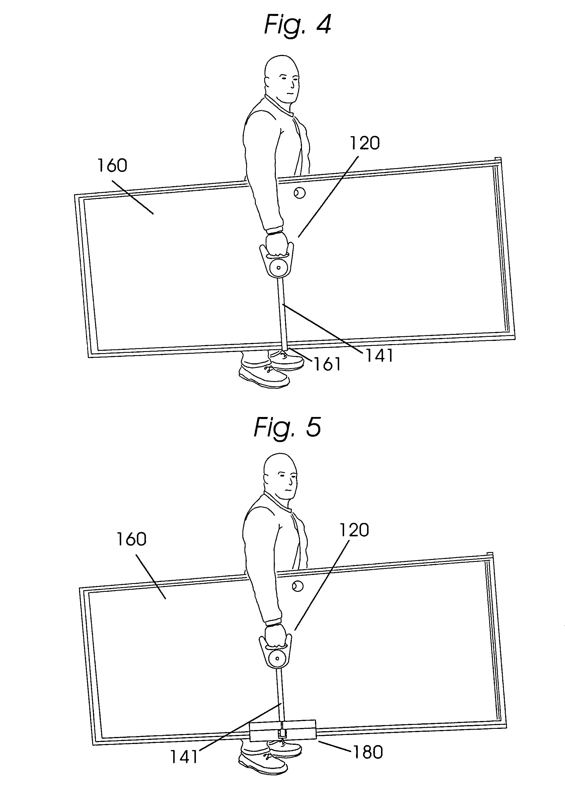
[0019]Yet another advantage of the invention is to provide a method of carrying heavy, large and / or awkward loads so that the mass of the load acts below the operator's center of gravity.

Problems solved by technology

Today, even though human beings now use elaborate and expensive machines to lift and transport things there is still an essential need for human beings to lift and transport things short distances with the power of human muscles.
Often, loads people carry with their bodies are heavy and the lifting situation is so awkwardly configured that people incur serious injury.
Torn muscles, back pain and worse are often the consequence of trying to lift and carry loads carelessly.
Hand trucks, wheel barrows are very useful but these devices are often limited by rough ground or the need to go up or down stairs.
The problem is so common for people that it is probable that no-one in their lifetime has escaped hurting themselves through activities like this.
When used by one person the load hangs in front of the person, pulls them forward and makes walking difficult.
A load carried this way seriously unbalances a person.
It is also difficult to bend down and pick up a heavy load and, once supported, the load is not very stable since it may easily slip off the hand platforms.
The dimensions of the load this device can carry is very limited.
Attaching the suitcases to the lifting appendages is awkward and time consuming and the user's arms must be held out from the body to avoid them bumping them into either the lifting appendages or the load.
Since the suitcases are directly attached to appendages hanging down from a position under the users arms they tend to rub and bump against the lifters body and legs.
Also, the lifter's hands are not directly available to manipulate the load.
Walking can be awkward with this device, however.
Ripoyla, et al, stipulates that one person can use the system but it is evident that the effectiveness of the method drops off significantly with only one operator.
Without another person to balance against, the load operator must lean back to support the load and walking then becomes very difficult.
One must conclude that lifting effectiveness and mobility is much impaired with one operator.
The mobility of prior systems is extremely limited.
None of the methods address the problems involved when one person must stoop or bend to pick up heavy loads.
The heavier the load, the more physical strength is needed and the greater the risk for injury.
None of the systems address physical stress and strain caused by the user having to accommodate and manipulate a very heavy load applied high up on their body.

Method used


Image

  • Machine and process for personal, side mounted biomechanically engineered lifting device; a device for lifting awkward and heavy loads
  • Machine and process for personal, side mounted biomechanically engineered lifting device; a device for lifting awkward and heavy loads
  • Machine and process for personal, side mounted biomechanically engineered lifting device; a device for lifting awkward and heavy loads

Examples


Embodiment Construction

[0059]Detailed descriptions of the preferred embodiments are provided herein. It is to be understood, however, that the present invention may be embodied in various forms. Therefore, specific details disclosed herein are not to be interpreted as limiting, but rather as a basis for the claims and as a representative basis for teaching one skilled in the art to employ the present invention in virtually any appropriately detailed system, structure or manner.

[0060]In accordance with the present invention, a side-mounted biomechanical lifting harness 100 is shown fitted to a person 99 about to lift a load. The shoulder load harness means 101 shown in FIG. 1, crosses the user's body diagonally and is connected by an adjustable harness buckle connector means 102. The load harness is adjusted so that the harness-load support means 103 supports the load height adjustment strap 110 and the load support ring 104 at or below the user's waist. The load height adjustment strap 110 is designed to ...


PUM


Abstract

The side-mounted, biomechanically designed lifting device maximizes the lifting capability of human anatomy. A harness with a shoulder pad crosses the user's body diagonally. The load is supported by an adjustable load strap at the user's side from a support ring attached to the harness. One end of the support strap is attached to the harness and the other to a lifting handle. With this device and method heavy and awkward loads like plywood and drywall may be carried and manipulated easily. The side-mounted lifting harness causes the user to lean away from the load. This transfers the weight of a load to a point near the ground, below the vertical center of gravity of the user and between the lifter's feet. There is significant biomechanical advantage to this load configuration. One person can carry heavy, awkward loads safely and quickly with a minimum of physical stress.

Description

CROSS REFERENCE TO RELATED APPLICATIONS[0001]Not ApplicableSTATEMENT REGARDING FEDERALLY SPONSORED RESEARCH OR DEVELOPMENT[0002]Not ApplicableDESCRIPTION OF ATTACHED APPENDIX[0003]Not ApplicableBACKGROUND OF THE INVENTION[0004]This invention relates generally to the field of transportation and more specifically to a machine and process for a personal, side mounted biomechanically engineered lifting device; a means of lifting awkward and heavy loads easily and safely.[0005]The rise of human civilization can be attributed, in part, to humankind's ability to transport food, materials and manufactured items significant distances. In the distant past, before the domestication of beasts of burden, this was done with human muscle power alone. The historical record depicts that ancient peoples used simple devices to augment the power of their muscles in order to create monuments of surprising scale. It is generally agreed, for example, that the ancient Egyptians created the pyramids without...

Claims


Application Information

Patent Timeline
Patent Type & Authority Patents(United States)
IPC IPC(8): A45F3/14
CPCA45F3/14A45F2003/146
Inventor BURTON, ALAN CLIFFORDCUNNINGHAM, JOHN JOSEPH
Owner BURTON ALAN CLIFFORD
Learn More