Tightening structure using high-strength self-forming screws

a self-forming screw and tightening technology, applied in the direction of fastening means, screws, couplings, etc., can solve the problems of fatigue fracture, unavoidable size reduction in comparison with conventional bolts, fuel efficiency, environmental friendliness, etc., to improve the strength of the bolt and the fatigue strength of the tightening thread ridge, the effect of strengthening the tightening

Active Publication Date: 2011-05-10
TOPURA CO LTD
View PDF15 Cites 13 Cited by
  • Summary
  • Abstract
  • Description
  • Claims
  • Application Information

AI Technical Summary

Benefits of technology

[0009]In consideration of the points described above, an object of the present invention is to provide a tightening structure with which a reduction in processing steps is achieved without modifying the shape of a partner member (nut member), the strength of a bolt is increased, and fatigue fractures are avoided, and with which the fitting length of a thread ridge is not altered greatly in comparison with a conventional tightening structure such that a size reduction can be achieved safely and effectively, thereby contributing greatly to a reduction in the weight of a vehicle.
[0011]As a result, there is no need to modify the shape of the partner member into which the self-forming screw is screwed, and therefore a reduction in the number of processing steps of the partner member can be achieved. Moreover, no clearance is generated on a contact surface between an external (male) screw and an internal (female) screw by the self-forming screw having a strength of 14T, which gradually self-forms the internal screw, and stress on a first engagement screw root portion of the nut member, in which stress is most concentrated, can be reduced through dispersion while strengthening the tightening. As a result, improvements in the strength of the bolt and the fatigue strength of the tightening thread ridge can be realized, and since the fitting length of the thread ridge is not altered greatly in comparison with a conventional tightening structure, a size reduction can be achieved effectively, thereby contributing greatly to a reduction in the weight of a vehicle.

Problems solved by technology

This point is a well-known technical problem, as described in Japanese Unexamined Patent Application Publication 2005-29870 and so on, for example.
Accordingly, advancing the use of high-strength bolts having a strength of 14T (minimum tensile strength 1400 N / mm2, hardness 44 to 47 HRC), which is the maximum strength that can be put to practical use at present, in place of conventional bolts to achieve dramatic size reductions in comparison with conventional bolts has become an unavoidable problem in terms of fuel efficiency, environmental friendliness, and so on.
Accordingly, in recent years, the development of bolts having maximum strength has become a technological problem requiring urgent attention.
If the bolt alone is increased in strength, a load on a thread ridge fitting portion of the nut member increases, leading to a large offset load on a root portion of a first fitting thread of the nut member, which may lead to a fatigue fracture in a corresponding location.
In addition to fatigue fractures, the nut member may be unable to withstand a tightening force of 14T, which is applied during static tightening performed to achieve tightening, and as a result, the internal screw part may break.
However, these elements vary according to relative pitch errors with the combined nut, the spring constant of a bolt / nut fastener, and tightening axial tension variation, and therefore rolling after heat treatment is performed to obtain a greater increase in the fatigue limit.
However, when rolling after heat treatment is performed on a high-strength bolt having a strength of 14T (minimum tensile strength 1400 N / mm2, hardness 44 to 47 HRC), a rolling tool is subjected to severe wear, and as a result, the life of the tool decreases to 1 / 10 of a tool used in heat treatment after rolling.
It is therefore impractical in terms of productivity and cost to improve the fatigue strength of a bolt having a strength of 14T by performing rolling after heat treatment.
However, the value of the pitch error used in this method must be managed in μm units, and therefore this method is likewise impractical in terms of productivity and cost.
Hence, at present, no effective solutions exist for increasing the fatigue limit.

Method used


Image

  • Tightening structure using high-strength self-forming screws
  • Tightening structure using high-strength self-forming screws
  • Tightening structure using high-strength self-forming screws

Examples


Embodiment Construction

[0019]Preferred embodiments of the present invention will become evident from the following description with reference to the attached drawings.

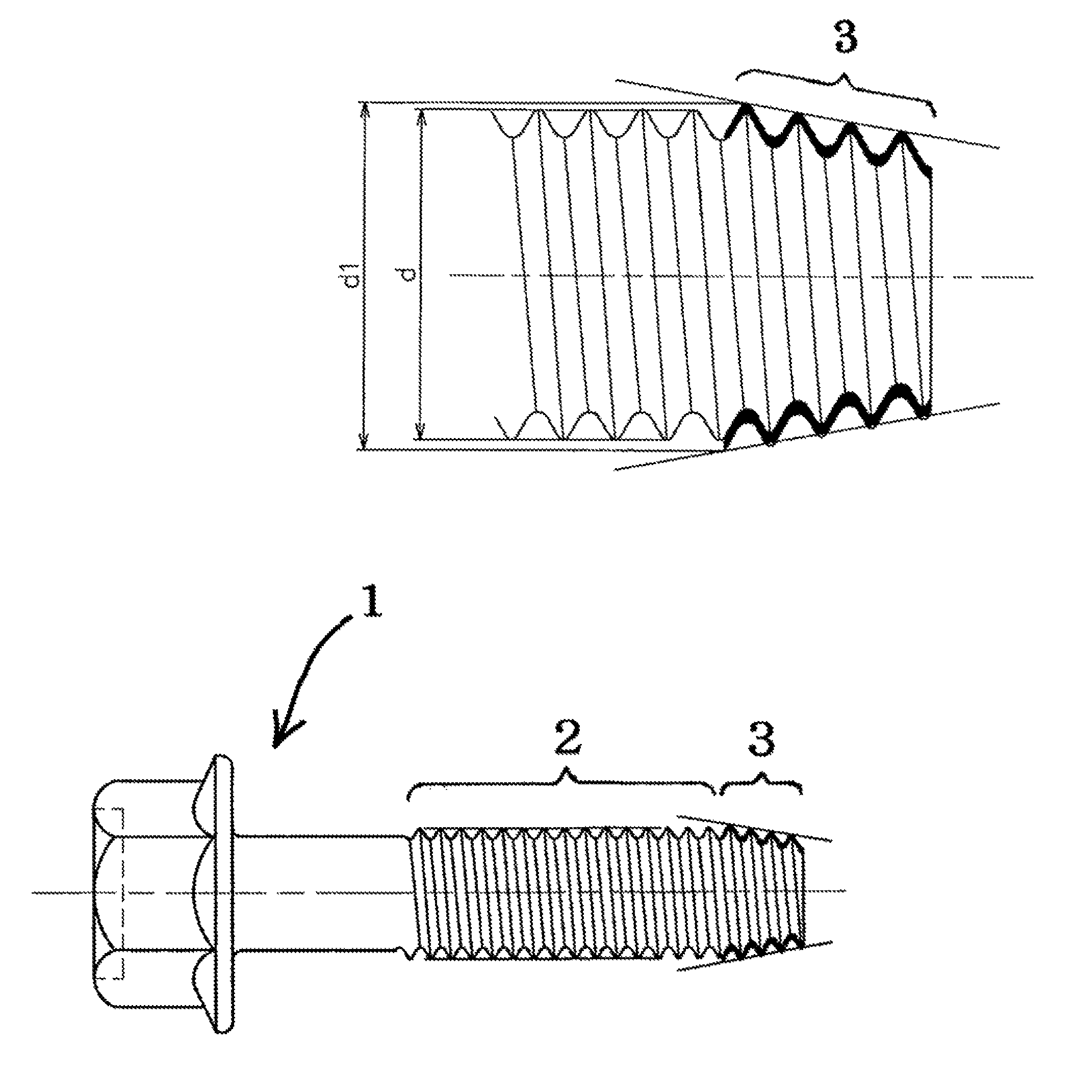
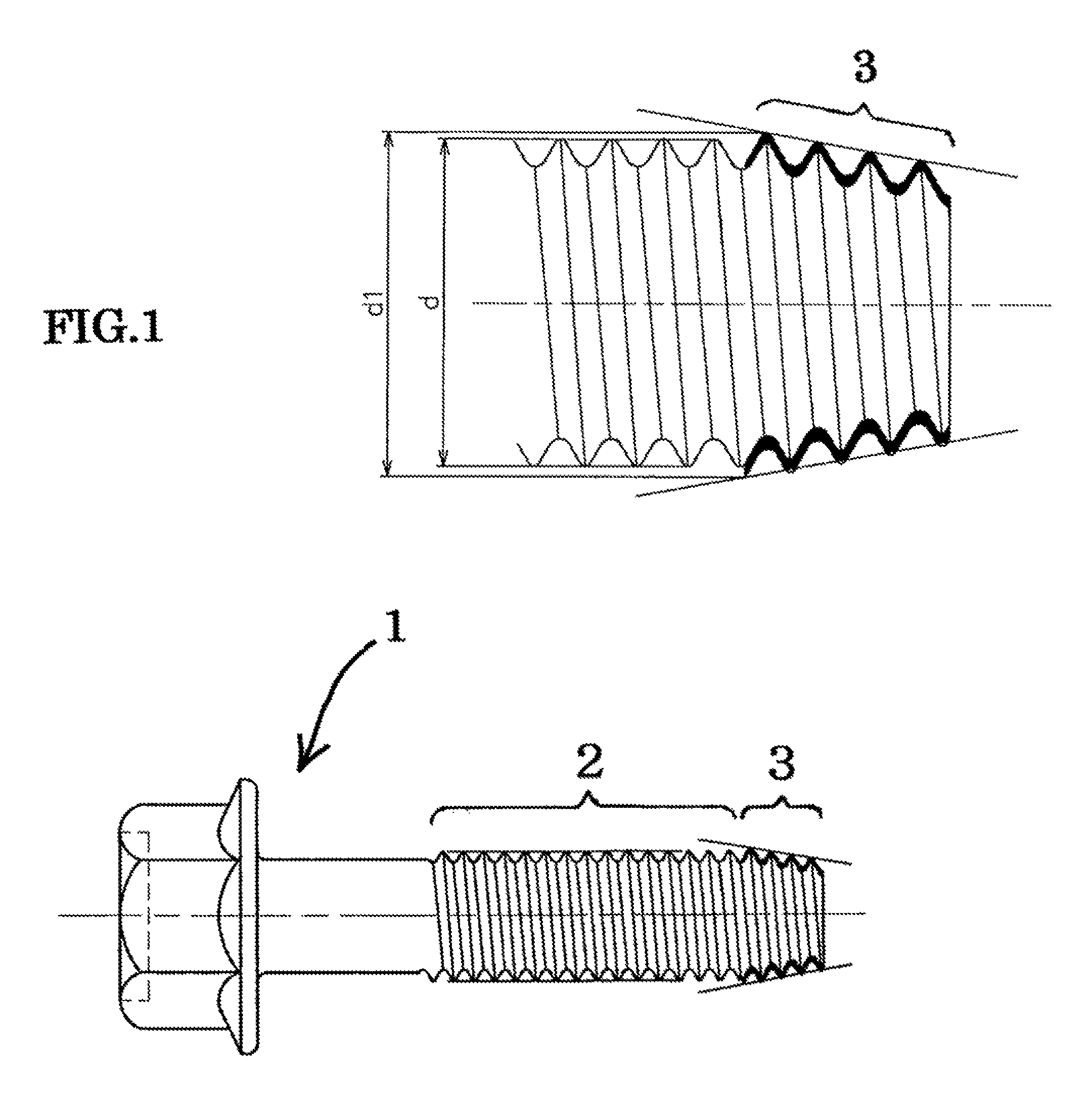
[0020]F1G. 1 shows a self-forming screw 1 used in the present invention. The self-forming screw 1 is a steel screw manufactured by pre-heat treatment rolling and having a strength of 14T (minimum tensile strength 1400 N / mm2, hardness 44 to 47 HRC). A thread portion thereof is constituted by a tapered self-forming thread portion 3 and a parallel thread portion 2 for performing normal tightening. The self-forming thread portion 3 is formed over a range of 1 to 5 pitches, and a maximum outer diameter or hypothetical outer diameter thereof d1 is between 1 and 10% larger than the outer diameter d of an external screw of the parallel thread portion 2. The hypothetical outer diameter denotes the diameter of a column formed hypothetically by the tip ends of projections when projections are provided on the thread portion of the self-forming thread po...


PUM


Abstract

The present invention provides a tightening structure with which a reduction in processing steps is achieved without modifying the shape of a partner member an improvements in bolt strength and fatigue strength are achieved, and with which the fitting length of a thread ridge is not altered greatly in comparison with a conventional tightening structure such that a size reduction can be achieved, thereby contributing greatly to a reduction in the weight of a vehicle.

Description

[0001]This application claims priority Japanese Patent Application No. JP2008-182482 filed on Jul. 14, 2008, which is incorporated here by reference.BACKGROUND OF THE INVENTION[0002]1. Field of the Invention[0003]The present invention relates to a tightening structure for performing tightening using high-strength self-forming screws (bolts).[0004]2. Description of the Related Art[0005]In a conventional tightening structure for tightening a peripheral site of an engine using high-strength bolts, the high-strength bolt is screwed to an internal (female) screw of a nut or an internal screw tapped into a partner member. An internal thread portion of a nut or a tapped internal screw hole is of course formed by a cutting process. When an internal screw hole is formed by performing a tapping process on an aluminum die-cast member, a chassis or suspension member, a forged member, or the like in a peripheral site of an engine, for example, precision is required in the hole diameter, and ther...

Claims


Application Information

Patent Timeline
Patent Type & Authority Patents(United States)
IPC IPC(8): F16B25/00
CPCF16B25/0021Y10T403/75
Inventor MORI, SHIGETOUMADA, AKIHIDEMATSUNO, MAYUMI
Owner TOPURA CO LTD
Why Eureka
Try Eureka