
Systems and methods for generating electricity from carbonaceous material with substantially no carbon dioxide emissions

a technology of carbonaceous material and electricity generation method, which is applied in the direction of energy input, machines/engines, mechanical equipment, etc., can solve the problems of increasing the cost of fossil fuel-based electricity production using existing technologies, increasing the cost of fossil fuel-based electricity production, and achieving little or no carbon dioxide emissions

Inactive Publication Date: 2011-05-10
PIONEER ENERGY
View PDF10 Cites 27 Cited by
  • Summary
  • Abstract
  • Description
  • Claims
  • Application Information

AI Technical Summary

Benefits of technology

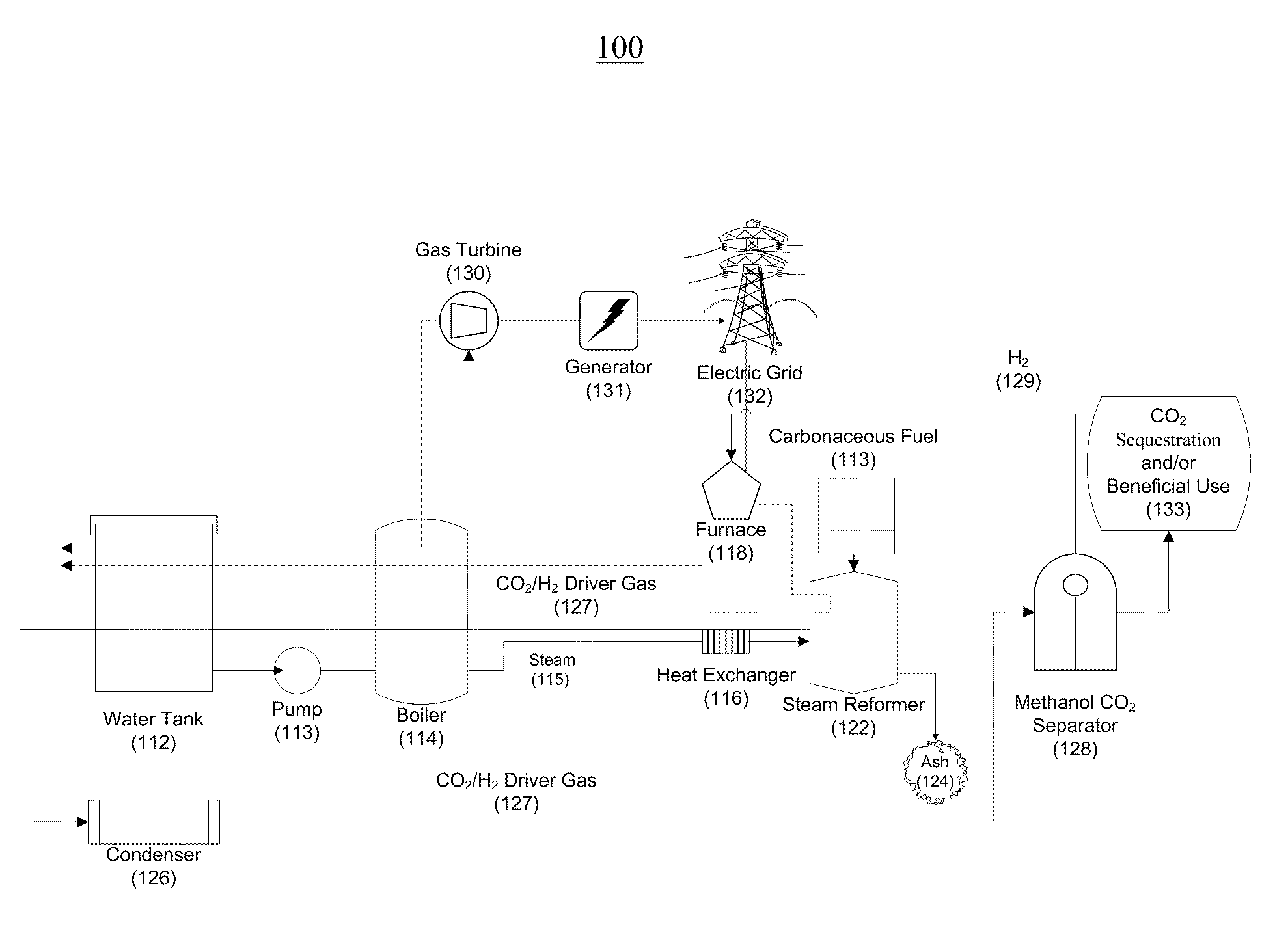
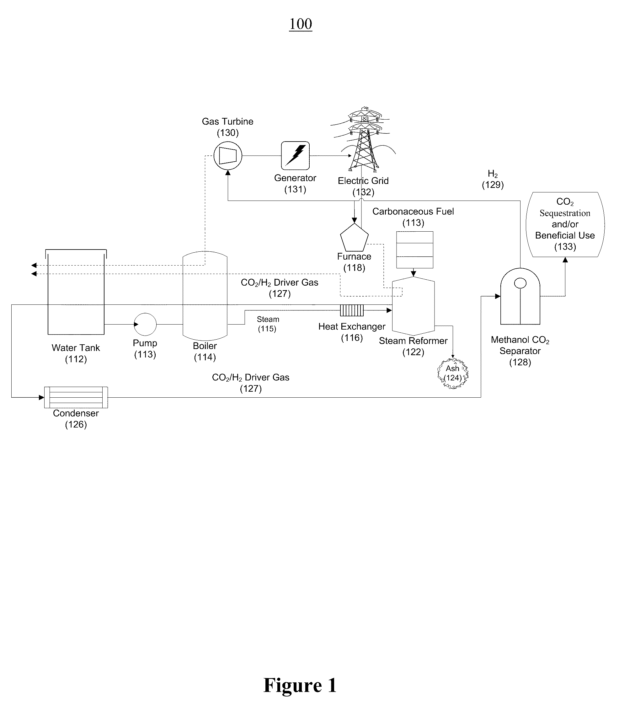
"The present invention is a power plant that generates electricity with low carbon dioxide emissions. It uses a boiler to generate steam, which is then converted into high-pressure gas by a steam reformer. The high-pressure gas is then separated from the rest of the gas and utilized to generate electricity. The power plant can use various carbonaceous materials, such as coal, biomass, natural gas, crude petroleum, ethanol, methanol, and trash, as the carbonaceous material. The electricity generated has a low carbon dioxide content and can be used in industrial processes or sequestration. The power plant can also include a heat exchanger, a condenser, a compressor, and a control system to manage the process."

Problems solved by technology

Fossil fueled, especially coal-fired, plants make reductions difficult.
Carbon capture and storage (CCS) of emissions from coal-fired power stations is another alternative but the technology is still being developed and will increase the cost of fossil fuel-based production of electricity using existing technologies.
Existing CCS technologies may not be economically viable, unless the price of emitting CO2 to the atmosphere rises.

Method used


Image

  • Systems and methods for generating electricity from carbonaceous material with substantially no carbon dioxide emissions
  • Systems and methods for generating electricity from carbonaceous material with substantially no carbon dioxide emissions
  • Systems and methods for generating electricity from carbonaceous material with substantially no carbon dioxide emissions

Examples


Embodiment Construction

[0039]This innovative plant design utilizes efficient reformation of carbonaceous fuel and steam to improve upon traditional combustion methods of fuel and air which currently dominate the power generation industry. The reformation of carbonaceous fuel allows power plants to contribute to the hydrogen economy by producing hydrogen for less energy than it takes to create it. This design also allows for sequestration and / or beneficial use of CO2 for a variety of applications such as the recovery of otherwise inaccessible oil, fire extinguishers, welding, pneumatic systems, biological applications, and chemical processing.

[0040]The hydrogen is either burned to produce clean electricity, to be sold to utilities or used for other uses such as a chemical production, fuel cell application, or enhanced oil recovery, depending on which of these methods produce higher monetary value to the operator.

[0041]If biomass is used as the fuel source, as a result of the fact that the CO2 injected into...


PUM


Abstract

A reformation power plant generates clean electricity from carbonaceous material and high pressure CO2 which can be easily sequestered or utilized for a beneficial purpose, such as fuel production. The reformation power plant design utilizes a reformation process that reforms carbonaceous fuel with super-heated steam into a high-pressure gaseous mixture that is rich in carbon dioxide and hydrogen gas. This high-pressure gas exchanges excess heat with the incoming steam from a boiler and continues onward to a condenser. Once cooled, the high-pressure gas goes through a methanol separator, after which the CO2-rich gas is sequestered underground or beneficially re-used. The remaining hydrogen-rich gas is combusted through a gas turbine. The gas turbine provides power to a generator and also regenerative heat for the boiler. Finally, the generator converts mechanical energy into electricity, which is transferred to the electric grid. Therefore, carbon-free electricity is generated from coal, biomass, or other carbon-based feedstock.

Description

REFERENCE TO RELATED APPLICATIONS[0001]This application is related to U.S. Ser. No. 12 / 496,456 entitled “A PORTABLE RENEWABLE ENERGY SYSTEM FOR ENHANCED OIL RECOVERY (PRESEOR) USING BIOMASS HAVING NET NEGATIVE CO2 EMISSIONS AND FOR GENERATING ELECTRICITY HAVING ZERO CO2 EMISSIONS,” filed on Jul. 1, 2009, the entirety of which is hereby incorporated by reference herein.FIELD OF THE INVENTION[0002]This invention relates to a system and method for generating “green electricity” having substantially zero or very low CO2 emissions from a carbonaceous feedstock. One embodiment of the present invention is a power plant which utilizes a steam reforming process that may be used to generate electricity, hydrogen, and high pressure carbon dioxide-rich gas, which may be either sequestered or utilized for a beneficial purpose (such as fuel production).BACKGROUND OF THE INVENTION[0003]The world's power demands are expected to rise 60% by 2030. With the worldwide total of active coal plants over 5...

Claims


Application Information

Patent Timeline
Patent Type & Authority Patents(United States)
IPC IPC(8): F02C6/18
CPCF01K13/00F01K23/067F02C3/28B01D2257/504C01B2203/84C01B2203/86Y02E20/18Y02E20/185Y02E50/11Y02E50/12Y02E20/16Y02E20/32Y02E50/10Y02P20/129Y02P30/00
Inventor ZUBRIN, ROBERT M.BERGGREN, MARK H.
Owner PIONEER ENERGY
Learn More