
Method for antimissile protection of vehicles and implementing device

a vehicle and anti-missile technology, applied in the direction of offensive equipment, instruments, transportation and packaging, etc., can solve the problems of a single individual firing a single missile, a significant threat, and a very short response time to counter the threat, and achieve the effect of short response tim

Inactive Publication Date: 2011-04-26
THALES SA
View PDF16 Cites 11 Cited by
  • Summary
  • Abstract
  • Description
  • Claims
  • Application Information

AI Technical Summary

Benefits of technology

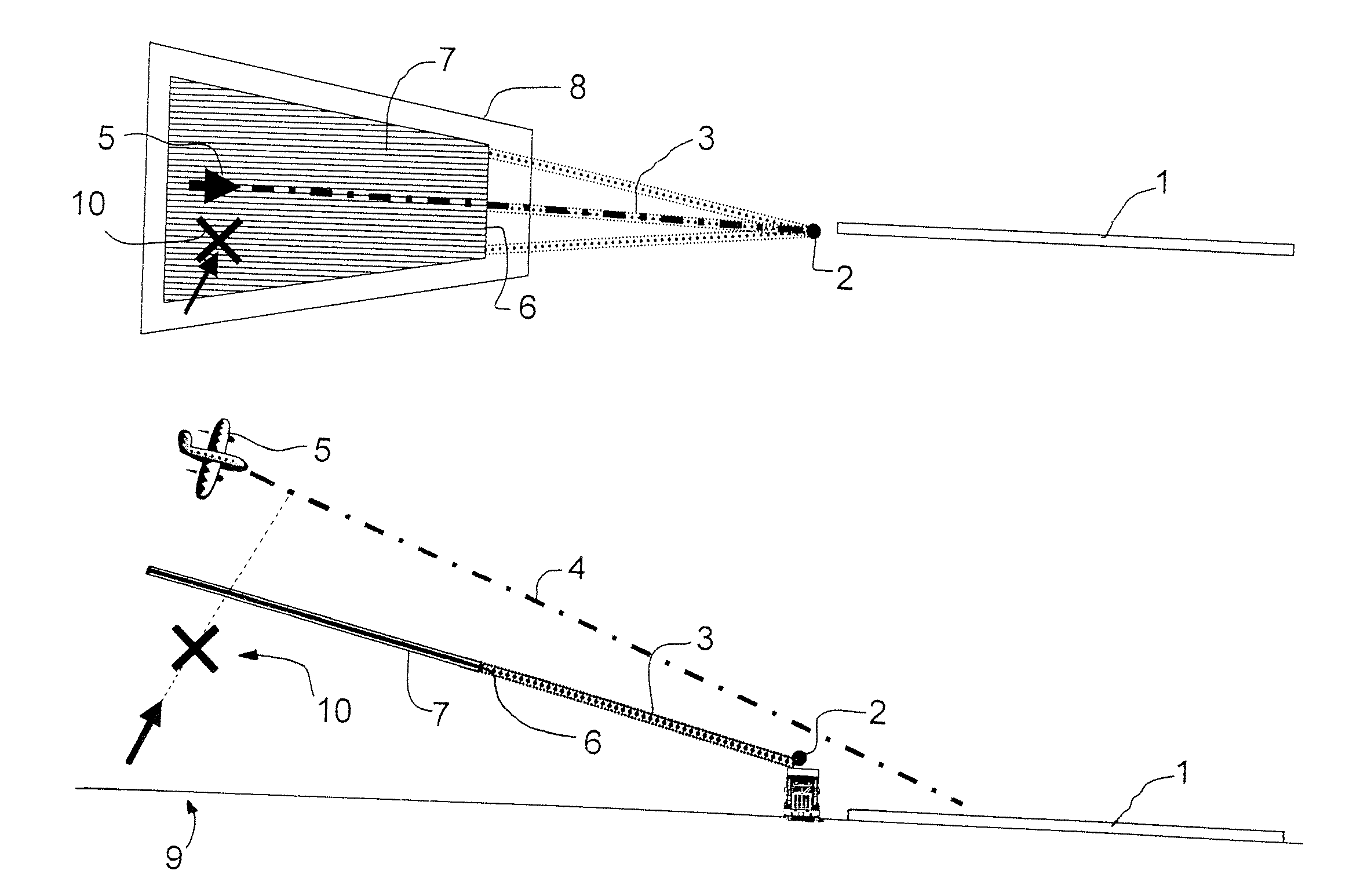
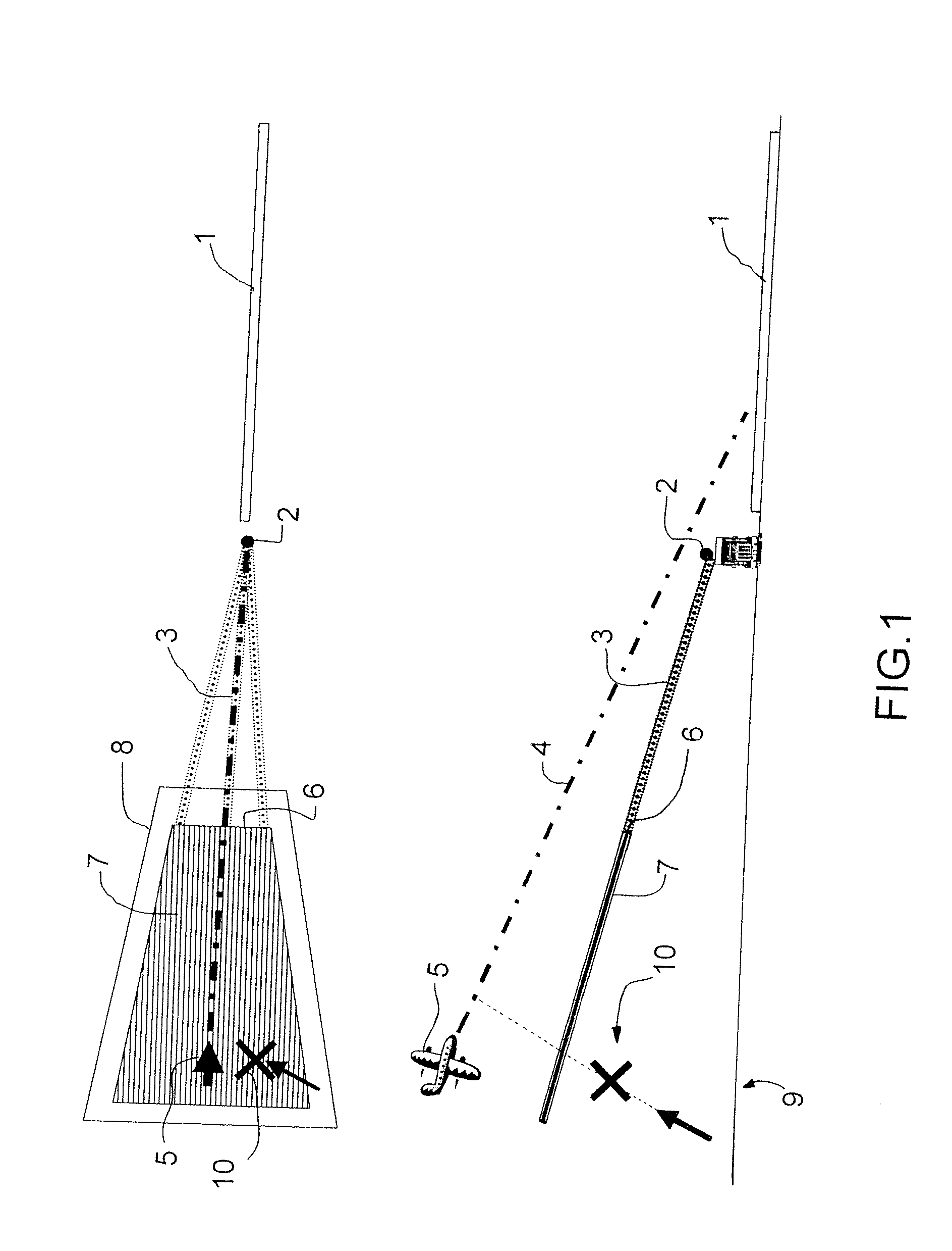
The present invention provides a method and device for antimissile protection of vehicles that has a very short response time with practically no false alarms and not requiring the use of means such as decoys or conventional laser jammers. The method involves creating a curtain of plasma filaments close enough together to produce an almost continuous ionized layer to blind the target-seeking device of the missiles. The plasma curtain is created by a laser beam sweeping a corresponding portion of space in a plane perpendicular to the probable trajectory of missiles on the approach to threatened vehicles. The antimissile protection device includes a pulsed laser, a device for controlling the spectral phase of the laser, and a spatial sweep device for orienting the laser beam in various directions in space. The technical effects of the invention are that it provides the best possible protection against missile threats and is simple, light, and economical.

Problems solved by technology

Portable missiles, fired by a single individual, are a significant threat, both from a military point of view and with respect to possible terrorist use.
The use of a method of detection then a countermeasure to the threat requires a very short response time compared with the minimum flight time of a missile, since missile flight times are short.
This constraint results in a potentially high rate of false alarms.
If the system is mounted on an aircraft or a vehicle, the cost and the weight of the system are major factors in the selection of the solution.
Moreover, the integration of optronic countermeasure systems into fleets which are already operational can be achieved by the addition of a detachable “pod” which may alter the aerodynamic characteristics of the carrier, which affects the consumption.
The use of decoys, such as infrared jamming canisters, is not possible near civil airports, because of the fire risks inherent in such devices.

Method used


Image

  • Method for antimissile protection of vehicles and implementing device
  • Method for antimissile protection of vehicles and implementing device
  • Method for antimissile protection of vehicles and implementing device

Examples


Embodiment Construction

[0020]In brief, the invention includes making a plasma curtain by using a laser placed in a particular area. The purpose of the protective screen formed by this curtain is to prevent the homing devices of missiles from locking on to the target. The invention uses the properties of ultrashort laser pulses (preferably with a duration of less than 10 ps) to create filaments of plasma by ionizing the air. In fact, a laser pulse which spreads through the atmosphere can be focused on a given point in space to create a plasma at this point. Along the extension of this point a filament is then produced in the propagation axis of the beam. This filament spreads over long distances (up to several kilometers) and has emissivity properties like those of a black body brought to high temperature (>1000 K up to 3000° K.). This filament typically has a diameter of a few hundred microns.

[0021]The laser used by the invention is a pulsed laser, having a pulse repetition frequency for example between 1...


PUM


Abstract

The present invention relates to a method for antimissile protection of vehicles having a very short response time with practically no false alarms and not requiring the use of means such as decoys or conventional laser jammers, while providing the best possible protection. It is characterized in that at least one curtain of plasma filaments is created between these vehicles and the probable launch point of these missiles, this curtain being intended to blind the target-seeking device of the missiles.

Description

CROSS-REFERENCE TO RELATED APPLICATIONS[0001]The present Application is based on International Application No. PCT / EP2006 / 062972 filed on Jun. 7, 2006, which in turn corresponds to French Application No. 05 06178 filed on Jun. 17, 2005, and priority is hereby claimed under 35 USC §119 based on these applications. Each of these applications are hereby incorporated by reference in their entirety into the present application.FIELD OF THE INVENTION[0002]The present invention relates to a method for antimissile protection of vehicles and a device for using this method.BACKGROUND OF THE INVENTION[0003]The invention relates to the protection of vehicles such as aircraft (airplanes, helicopters) or ground vehicles (trucks, tanks) from the threat of missiles using infrared, TV or electromagnetic guidance, and more generally, missiles fitted with a target-seeking device, or associated with such a device.[0004]Portable missiles, fired by a single individual, are a significant threat, both from...

Claims


Application Information

Patent Timeline
Patent Type & Authority Patents(United States)
IPC IPC(8): F41H11/00
CPCF41H11/02G01S7/38H04K3/60H04K3/825G01S7/495H04K2203/24
Inventor MARQUIS, EMMANUELPOCHOLLE, JEAN-PAUL
Owner THALES SA
Learn More