
Method and arrangement in connection with inverter

a technology of inverter and arrangement, which is applied in the direction of power conversion systems, dc source parallel operation, electrical apparatus, etc., can solve the problems of diodes being overheated, increasing costs, and complicating spare parts service, so as to reduce the rate of voltage rise and the voltage of the load. , the effect of increasing the voltag

Inactive Publication Date: 2011-04-12
ABB OY
View PDF6 Cites 1 Cited by
  • Summary
  • Abstract
  • Description
  • Claims
  • Application Information

AI Technical Summary

Benefits of technology

[0013]The invention is based on generating voltage for a load with parallel sub-inverters in such a manner that the sub-inverters generate the same output voltage pattern, but, however, with mutually slightly delayed switchings. Cables, parallel-connected to the load only at their tail ends, implement, by means of their wave impedances, the voltage division acting in the motor poles at the time of the switching, enabling a gradual increase in the voltage of the load.
[0014]Since the coupling time of an individual sub-inverter remains the same in the arrangement of the invention, but the voltage increment taking place in the motor poles is lower, it means that the rate of voltage rise observed by the load, such as a motor, becomes lower such that the load cannot be damaged under the influence of the rate of voltage rise. The rate of voltage rise can also be lowered without separate components, such as inductors or filters, to be added to the output of the inverter.

Problems solved by technology

However, this procedure has a plurality of generally known drawbacks.
This increases costs and complicates spare part service.
However, matching the voltage loss of the IGBT switches does not usually mean that the voltage losses of the diodes parallel to the switches would be correspondingly matched; instead, extremely significant differences may exist, which may lead to some diodes being overheated.
This may cause situations wherein the fastest module switches on the entire phase current and, correspondingly, the slowest module switches off the entire phase current.
This results in a serious increase in switching losses and heating at these modules.
However, this technique does not work if there are many parallel-connected chips, since the short-circuit current of a defectively working chip is known not to be sufficient to draw correctly working chips off saturation; instead, the defectively working module explodes.
However, such inductors are bulky, they cause much dissipation power and are expensive.
This is not possible in the electrical safety prescriptions of several countries without a special permit; instead, in most cases, the requirement is that each of the rigidly interconnected sub-conductors, too, is protected against short-circuit and overload current either with a fuse, a relay function or current measurement.
These protective components are often expensive and require much space.
However, the latter method does not either eliminate the disadvantage that may result from the extremely fast IGBT switches switching their states in the coils and bearings of the motors.
In addition, the reflection phenomenon caused by the discontinuity point generated by the unequal wave impedances of the cables and the motor may, in the worst case, almost double the current peak appearing in the motor poles compared with the voltage level of the intermediate circuit outgoing from the inverter.
Such a voltage steepness and large amplitude are known to cause such high turn voltages, particularly in unfavorably coiled wire coils, that there exists the possibility of a partial discharge.
An extendedly acting partial discharge may finally damage the insulation of the winding wire, and the resulting turn short-circuit destroys the coil.
The surge wave propagating in the motor cables also causes capacitive polyphase currents via the ground potential, which puncture the lubricant membrane when passing through the motor bearings, thus shortening their service life.
However, these components are bulky and expensive.

Method used


Image

  • Method and arrangement in connection with inverter
  • Method and arrangement in connection with inverter
  • Method and arrangement in connection with inverter

Examples


Embodiment Construction

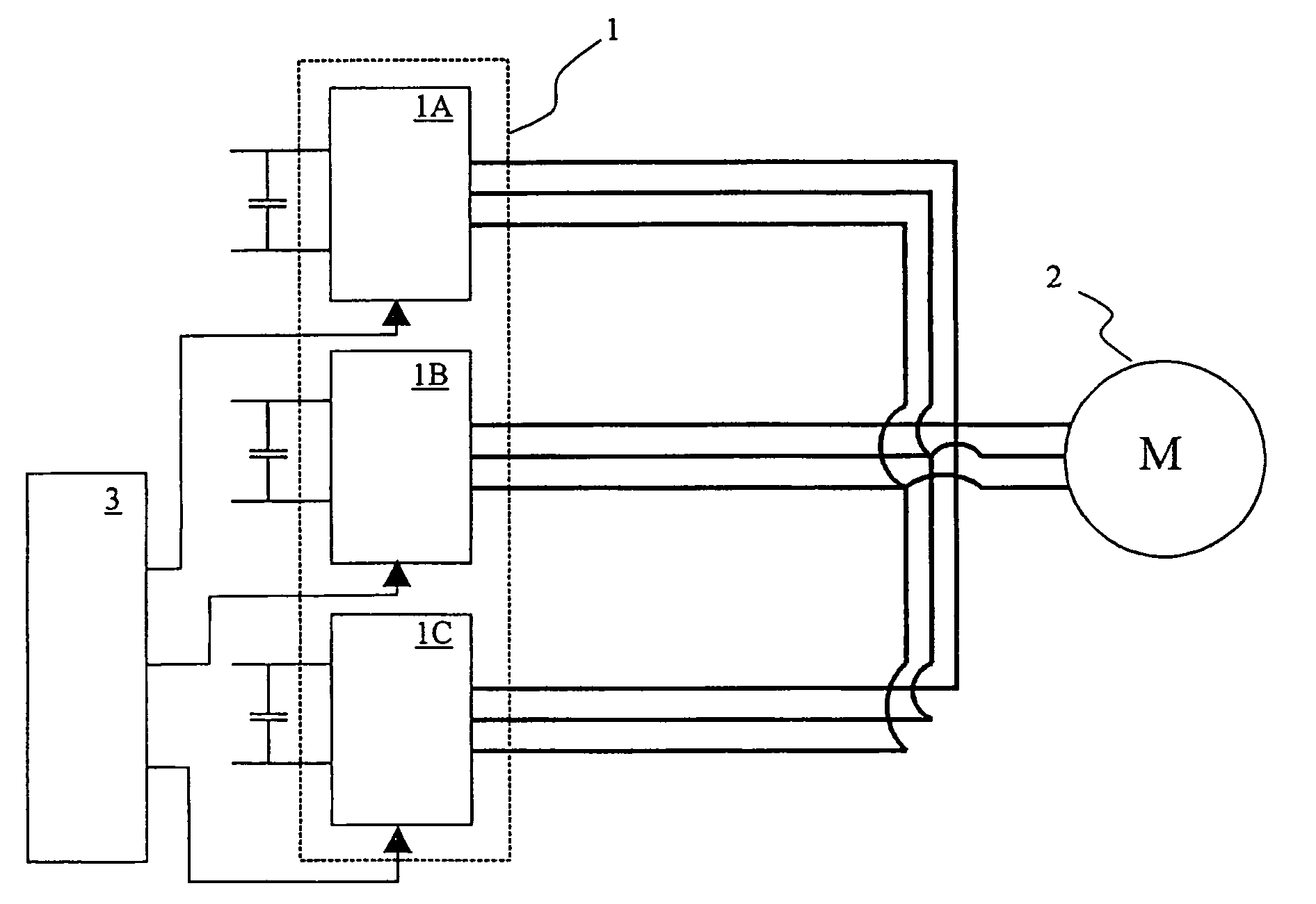
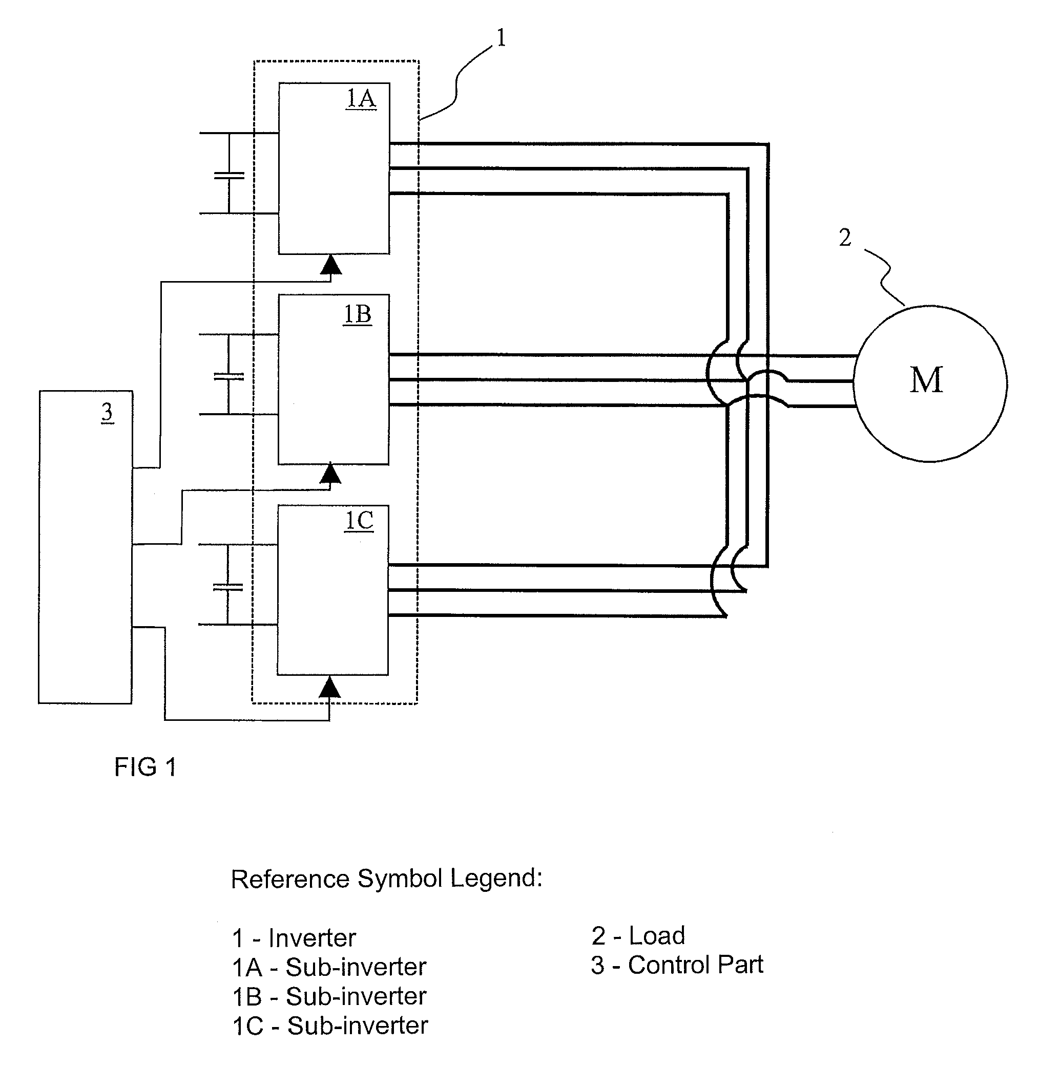
[0020]FIG. 1 shows the principle of sub-inverters 1A, 1B, 1C operating in parallel and together constituting an inverter 1, which is controlled to generate the desired voltage for a load 2. In the present description, a load refers to a motor, but it is clear, however, that the type of load bears no significance to the application of the invention.

[0021]The sub-inverters operating in parallel are connected to the load, each with a specific cable, and these sub-inverter cables are interconnected at the motor end and further connected to the load. The interconnection of the cables is naturally performed by interconnecting the corresponding phases of each cable. FIG. 1 shows this cable connection before the load in order to increase clarity. In real terms, this connection is performed in the motor conduit box or the like by using busbar structures, for example.

[0022]FIG. 1 also shows a control part 3 for controlling the inverter and for transmitting switching instructions to each sub-i...


PUM


Abstract

A method and an arrangement for controlling an inverter provided with a voltage intermediate circuit, the inverter (1) comprising two or more sub-inverters (1A, 1B, 1C), each being connected with a specific cable to feed a common load (2) and each sub-inverter (1A, 1B, 1C) receiving the same switch instruction pattern. The method comprises the steps of determining the magnitude of a time delay, and consecutively generating, with each sub-inverter (1A, 1B, 1C), an output voltage according to the switch instruction for the load (2) such that each sub-inverter generates an output voltage according to the switch instruction after a time equal to the time delay.

Description

BACKGROUND OF THE INVENTION[0001]The invention relates to a method and an arrangement in connection with an inverter. The invention relates particularly to controlling an inverter consisting of a plurality of sub-inverters, each being connected by a specific cable to feed a common load.[0002]The power stages of power inverters intended for the low-voltage range are usually composed of a plurality of parallel IGBT switch modules. Conventionally, the parallel connection is performed phase-specifically by rigidly interconnecting the switch module poles intended for feeding the same phase in the immediate vicinity of the modules, and by connecting the motor cable conductors of the same phase to said interconnection by means of suitable busbar arrangements.[0003]However, this procedure has a plurality of generally known drawbacks. In order for the phase current to be divided evenly between the rigidly parallel-connected switch module branches, the modules have to be selected to be as sim...

Claims


Application Information

Patent Timeline
Patent Type & Authority Patents(United States)
IPC IPC(8): H02M7/00
CPCH02M7/537H02M7/493
Inventor MIETTINEN, ERKKI
Owner ABB OY
Learn More