Diaphragm unit, light intensity adjusting device, lens barrel, and imaging apparatus

a technology of light intensity adjusting device and diaphragm unit, which is applied in the direction of camera diaphragm, optics, instruments, etc., can solve the problems of reducing the size of the lens barrel in the optical axis direction should be great, and the size of the imaging apparatus should be reduced, so as to reduce the size of the lens barrel, reduce the size of the imaging apparatus, and increase the length of the lens barrel

Inactive Publication Date: 2011-04-12
SONY CORP
View PDF13 Cites 1 Cited by
  • Summary
  • Abstract
  • Description
  • Claims
  • Application Information

AI Technical Summary

Benefits of technology

[0009]However, in the above-mentioned light intensity adjusting device, it is difficult to reduce the size (thickness) in an optical axis direction due to its structural restriction.
[0013]Thus, it is desirable to provide a diaphragm unit, a light intensity adjusting device, a lens barrel, and an imaging apparatus, which are advantageous for a decrease in size while guaranteeing the optical performance.
[0020]According to the above-mentioned embodiments of the invention, since the concave portion is disposed in one side surface of the receiving member receiving the diaphragm unit, it is possible to reduce the size of the lens barrel in the optical axis direction by receiving and arranging another optical device or a part thereof, or an optical member or a part thereof in the concave portion. Therefore, it is advantageous for the decrease in size of the imaging apparatus.
[0021]Alternatively, it is possible to guarantee the strokes of the movable lenses such as a zoom lens and a focus lens great without an increase in length of the lens barrel. Therefore, it is possible to guarantee the zoom ratio and to guarantee a focus adjusting range great, which is advantageous for the improvement in optical performance of the lens barrel.
[0022]Since an inexpensive lens with a relatively small refractive index and a large thickness can be used as the movable lens, it is advantageous for the decrease in cost of the imaging apparatus.

Problems solved by technology

However, in the above-mentioned light intensity adjusting device, it is difficult to reduce the size (thickness) in an optical axis direction due to its structural restriction.
Accordingly, when movable lenses such as a zoom lens and a focus lens are arranged before and after the light intensity adjusting device in the optical axis direction, the following problems are caused.
That is, when the strokes of the movable lenses are sufficiently guaranteed, the size of a lens barrel in the optical axis direction should be great, which is disadvantageous for a decrease in size of an imaging apparatus.
When the size of the lens barrel in the optical axis direction is limited, the strokes of the movable lenses may not be sufficiently guaranteed and thus a zoom ratio may be restricted, which is disadvantageous for an improvement in optical performance.

Method used


Image

  • Diaphragm unit, light intensity adjusting device, lens barrel, and imaging apparatus
  • Diaphragm unit, light intensity adjusting device, lens barrel, and imaging apparatus
  • Diaphragm unit, light intensity adjusting device, lens barrel, and imaging apparatus

Examples


first embodiment

[0064]Hereinafter, an embodiment of the invention will be described with reference to the accompanying drawings.

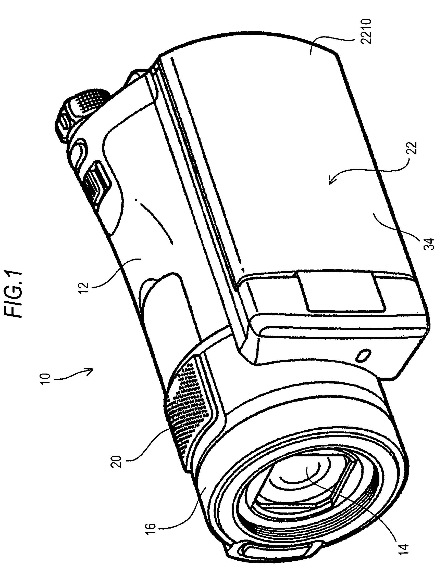
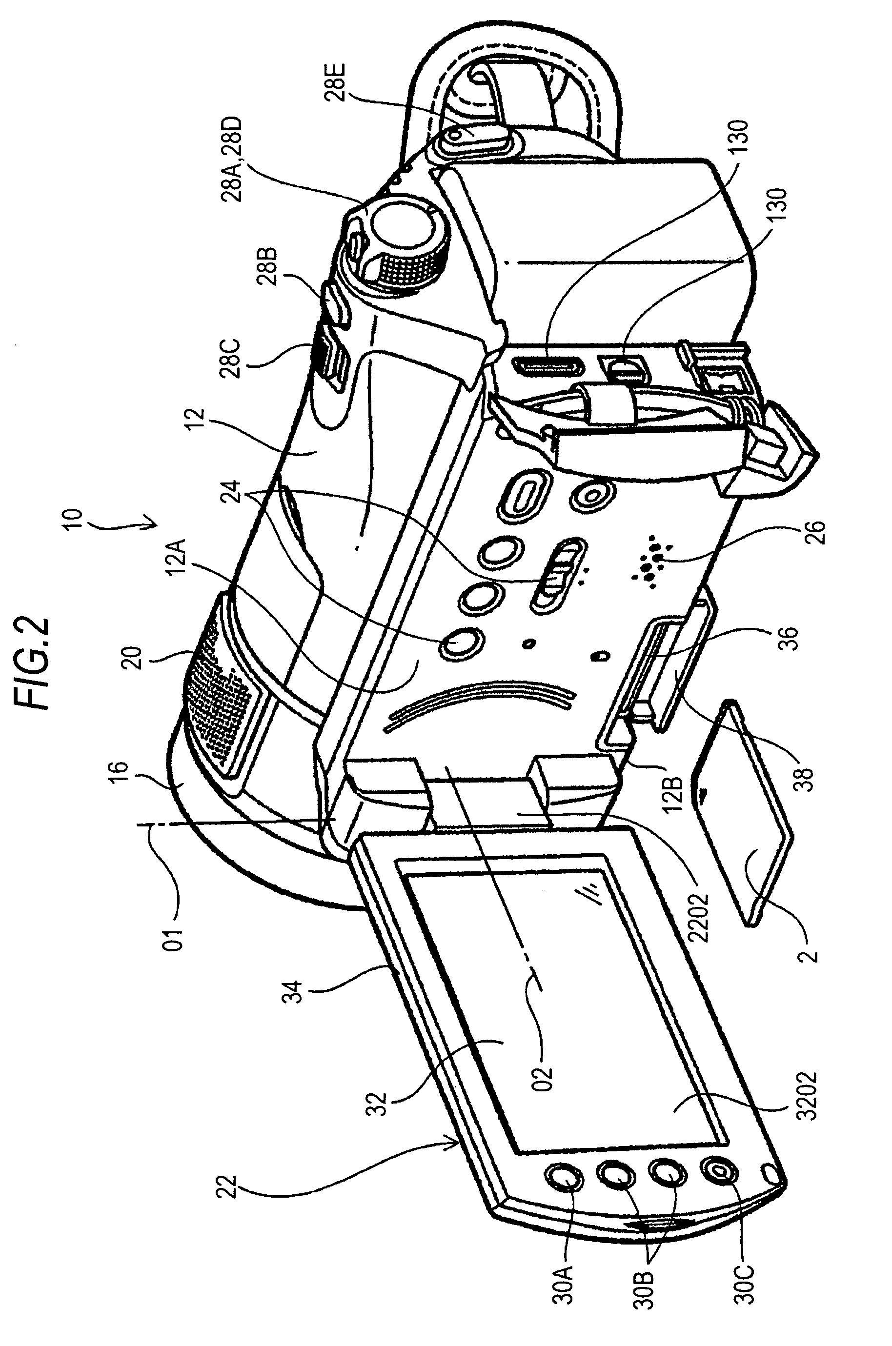
[0065]FIG. 1 is a perspective view of an imaging apparatus 10 according to an embodiment of the invention. FIG. 2 is a perspective view illustrating a state where a display panel 22 of the imaging apparatus 10 is located at an open position. FIG. 3 is a block diagram illustrating the configuration of a control system of the imaging apparatus 10.

[0066]The configuration of a control system of an imaging apparatus 10 will be described now with reference to FIG. 3.

[0067]In this embodiment, the imaging apparatus 10 is a moving image camera and serves to record data of taken moving images, still images, and sounds in a recording medium and to reproduce the data from the recording medium.

[0068]In this embodiment, a memory card 2 which is a plate-like or rod-like recording medium is used as the recording medium. However, a magnetic recording tape, an optical disk, a hard disk may ...

second embodiment

[0399]A second embodiment of the invention will be described now.

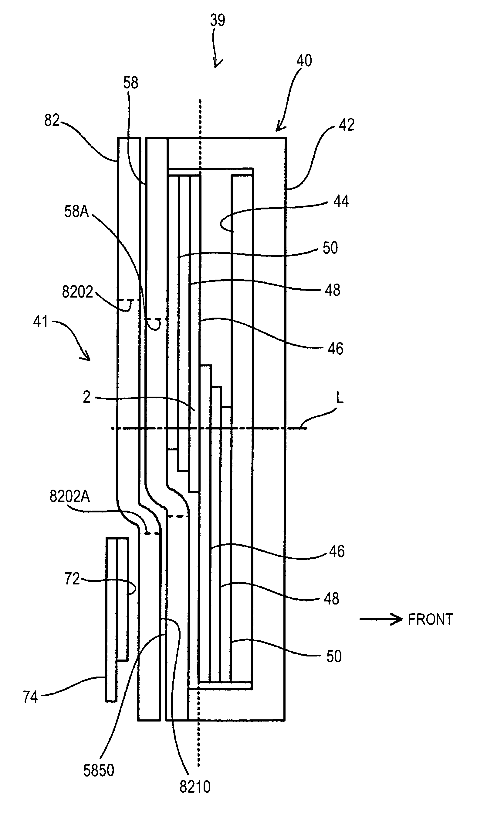
[0400]FIG. 38 is a sectional view of a light intensity adjusting device 39 according to the second embodiment of the invention.

[0401]The second embodiment is different from the first embodiment, in that the filter cover member 82 and the diaphragm cover member 58 are formed of a single member, as shown in FIG. 38.

[0402]When it is considered that the filter cover member serves as the diaphragm cover member 58 of the diaphragm unit 40, the concave portion 5850 is formed in the filter cover member 82.

[0403]When it is considered that the filter cover member 82 serves as the filter cover member 82 of the ND filter unit 41, the convex portion 8210 is formed in the filter cover member 82.

[0404]According to the second embodiment, since the filter cover member 82 and the diaphragm cover member 58 are formed of a single member, it is possible to reduce the size of the light intensity adjusting device 39 in the direction of the o...


PUM


Abstract

A diaphragm unit includes: a pair of straight-moving diaphragm blades and a pair of swing diaphragm blades overlapping with each other in an optical axis direction of an optical system and forming a diaphragm opening centered on the optical axis by moving in directions in which the diaphragm blades get close to and apart from the optical axis along a plane perpendicular to the optical axis; a receiving member receiving the pair of straight-moving diaphragm blades and the pair of swing diaphragm blades; and a diaphragm driving mechanism adjusting the size of the diaphragm opening by moving the diaphragm blades. The receiving member has a pair of side surfaces facing each other in the optical axis direction. One and the other of the straight-moving diaphragm blades and one and the other of the swing diaphragm blades are disposed on one and the other of the side surfaces, respectively.

Description

CROSS-REFERENCE TO RELATED APPLICATION[0001]The present application claims priority from Japanese Patent Application No. JP 2008-322330 filed in the Japanese Patent Office on Dec. 18, 2008, the entire content of which is incorporated herein by reference.BACKGROUND OF THE INVENTION[0002]1. Field of the Invention[0003]The present invention relates to a diaphragm unit, a light intensity adjusting device, a lens barrel, and an imaging apparatus.[0004]2. Description of the Related Art[0005]Portable imaging apparatuses such as moving image cameras and digital still cameras or projection-based optical apparatuses such as liquid crystal projectors are provided with a light intensity adjusting device.[0006]For example, the light intensity adjusting device includes a diaphragm unit adjusting the size of a diaphragm opening centered on an optical axis of an optical system and an ND filter unit reducing the light intensity passing through the diaphragm opening.[0007]As such a type of diaphragm ...

Claims


Application Information

Patent Timeline
Patent Type & Authority Patents(United States)
IPC IPC(8): G03B9/06
CPCG03B9/02
Inventor HATTORI, KAZUHIROAZUMA, RYUHEI
Owner SONY CORP
Why Eureka
Try Eureka