Optical fiber coating machine

A coating machine and optical fiber technology, applied in the field of optical fiber coating, can solve the problems of coating bubbles, achieve the effect of eliminating bubbles, ensuring coating effect, and reducing air thickness

Pending Publication Date: 2022-07-15
TAKFLY COMM
View PDF6 Cites 0 Cited by
  • Summary
  • Abstract
  • Description
  • Claims
  • Application Information

AI Technical Summary

Problems solved by technology

[0004] In order to improve the problem of air bubbles in the coating caused by air carried on the surface of the optical fiber in the prior art,

Method used


Image

  • Optical fiber coating machine
  • Optical fiber coating machine
  • Optical fiber coating machine

Examples


Embodiment Construction

[0041] The present application will be further described in detail below with reference to the accompanying drawings.

[0042] The embodiment of the present application discloses an optical fiber coating machine.

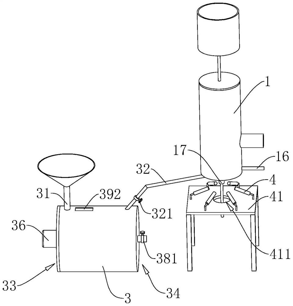
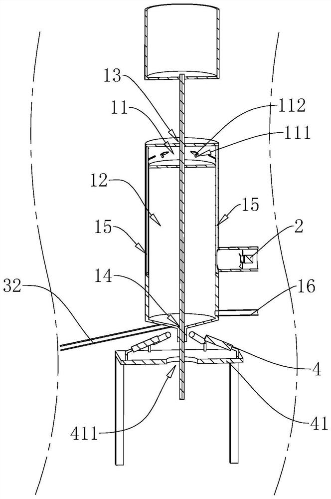
[0043] refer to figure 1 and figure 2 , an optical fiber coating machine, which includes: a coating tank, a coating box 1, an air supply machine 2 and a defoaming box 3. The defoaming box 3 is provided with a liquid inlet pipe 31 , the paint tank is communicated with the liquid inlet pipe 31 , and the defoaming box 3 is communicated with the coating box 1 , so that the paint enters the coating box 1 after removing bubbles from the defoaming box 3 . The coating box 1 has a transfer chamber 11 communicated with an optical fiber inlet 13 and a coating chamber 12 communicated with an optical fiber outlet 14 . The air supply machine 2 is installed on the coating box 1 and communicated with the transfer chamber 11. The air supply machine 2 supplies gas with low dynam...


PUM


Abstract

The invention discloses an optical fiber coating machine which comprises a coating box provided with an optical fiber inlet and an optical fiber outlet, and an optical fiber penetrates into the coating box through the optical fiber inlet and penetrates out of the coating box through the optical fiber outlet; the coating tank is communicated with the coating box and is used for supplying coating to the coating box; the coating box is provided with a transfer chamber and a coating chamber, an air supply machine is arranged on the coating box, the transfer chamber is communicated with the optical fiber inlet, and the coating chamber is communicated with the optical fiber outlet; and the air supply machine is communicated with the transfer chamber, and supplies air of which the dynamic viscosity is smaller than that of air into the transfer chamber. According to the optical fiber coating device, air brought in when optical fibers enter the coating box can be effectively reduced, and therefore bubbles generated in the coating process are reduced.

Description

technical field [0001] The present application relates to the technical field of optical fiber coating, in particular to an optical fiber coating machine. Background technique [0002] The optical fiber is composed of three parts: the core, the cladding and the coating layer. The function of the coating layer is to protect the surface of the optical fiber from being scratched by wet gas and external force, which endows the optical fiber with microbending resistance, improves the strength of the optical fiber, and reduces the optical fiber. Microbending additional loss. [0003] During the coating process of the optical fiber, if bubbles are generated in the coating, it will seriously affect the performance of the optical fiber. In the traditional technical solution, a sealing structure is usually used to prevent the optical fiber from carrying air into the coating box; however, since the optical fiber needs to slide into the coating box, it is unavoidable that there will be...

Claims


Application Information

Patent Timeline
Patent Type & Authority Applications(China)
IPC IPC(8): C03C25/104C03C25/12
CPCC03C25/104C03C25/12
Inventor 刘合一罗苗
Owner TAKFLY COMM
Why Eureka
Try Eureka