Retractable roof system for vehicles

a retractable roof and vehicle technology, applied in the field of retractable roof systems for vehicles, can solve the problems of limiting the capacity to transport items taller than the roofline of the shell, affecting the safety of workers, so as to facilitate the installation of the shell, facilitate the installation, and facilitate the installation

Inactive Publication Date: 2011-03-29
JOAB JACOB J
View PDF5 Cites 25 Cited by
  • Summary
  • Abstract
  • Description
  • Claims
  • Application Information

AI Technical Summary

Benefits of technology

[0019]The primary advantage the retractable roof system, vehicle and truck shell variation, is that the design offers a hard enclosure, with slidably adjustable roof panels, capable of stacking and stowing above the cab of a truck, or above the roof of a vehicle, opposite the end in which the roof panels are retracted.
[0020]Another advantage of the retractable roof system, truck shell variation is that it provides a convenient means for transporting large, oversized items in a truck, by opening the roof, and rear window of the enclosure, as opposed to removing the entire shell from the bed of the truck.

Problems solved by technology

These shells, however, limit the capacity to transport items taller than the shell's roofline.
Furthermore, the absence of hand-holds exposes the handler to pinch and laceration injury.
Lastly, if a strong second person is not available to assist in the removal, and subsequent reinstallation of the shell, the process of removal and installation by a single person is inarguably dangerous to a sole person removing or installing the shell.
The painted surfaces of both the truck and the truck shell may also be compromised during transition.
Standard shells are designed to be neither portable nor easily stowable.
Beyond the practical reasons already discussed, the inherent bulk of a standard truck shell limits the inventory of the typical shell to oversized racks, as seen in commercial yards or warehouses.
Automotive supply stores, membership club stores, and mega-mart outlets lack the floor space to stock a comprehensive array of brand-specific models, of various sizes and styles of a conventional truck shell.
It does not employ a hinged rear window panel, and does not allow the roof above the seating area to open.
This patent describes a portable truck cap or shell for pick-up trucks where portions are detachably connected to the truck but it does not provide the unique sliding capability of the roof panels to be stored over the truck cab.
It does not offer the heavy duty structural framework and unique support members to handle the weight of an additional lumber / sport rack, as provided by the retractable roof system, truck shell variation.
This patent describes a two-part pick-up truck cargo canopy assembly that emphasizes the need for opening the rear of the shell-covered area at times. The problem is that it uses a unitarily manufactured rear section that would be quite heavy and not easily stored.
This shell system could not be easily sold in an automotive parts store due to the large size and the inventory area required.
Although this patent describes a telescoping device, it is limited to just telescoping over the bed area and does not extend over the cab of the vehicle, and does not entirely retract from the truck bed cargo area.
This patent describes another two-part pick-up truck shell assembly that again emphasizes the need for opening the rear of the shell-covered area at times. The problem is still that it uses a unitarily manufactured rear section that would be quite heavy and not easily stored.
This device would not support a lumber / sport rack and does not provide security or the unique means of the sliding roof panels that can be stored over the cab of the truck.

Method used


Image

  • Retractable roof system for vehicles
  • Retractable roof system for vehicles
  • Retractable roof system for vehicles

Examples


Embodiment Construction

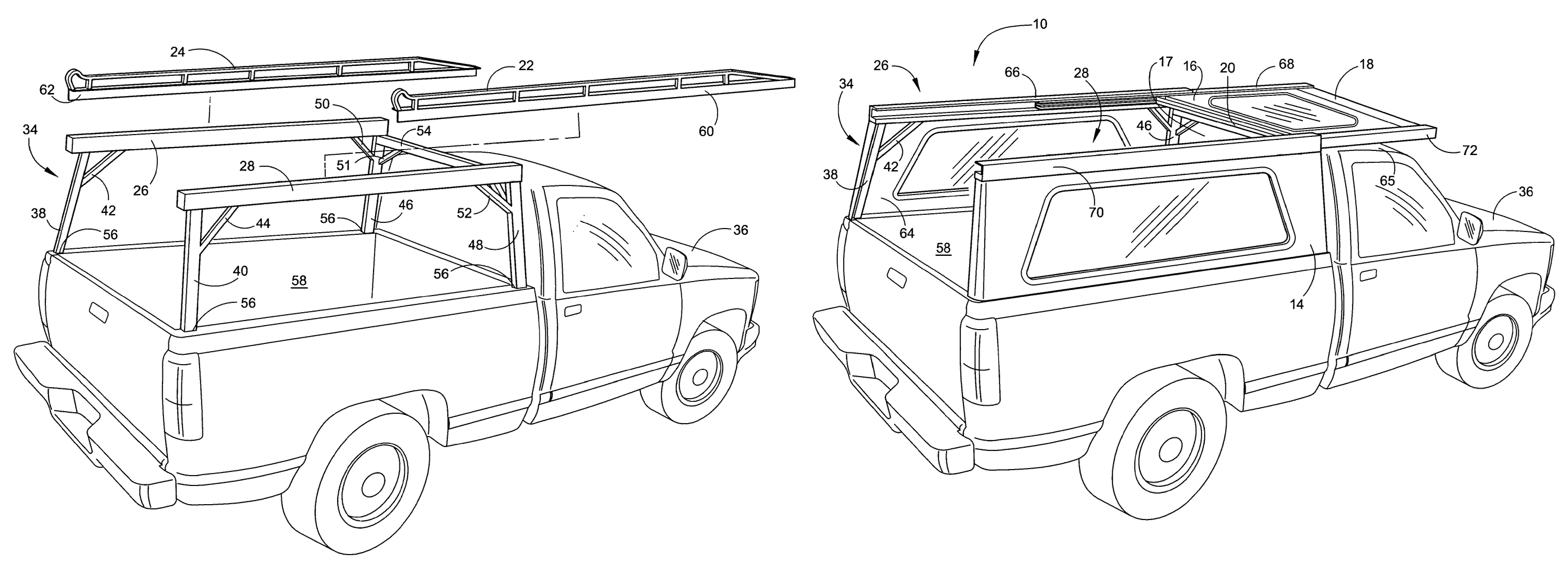
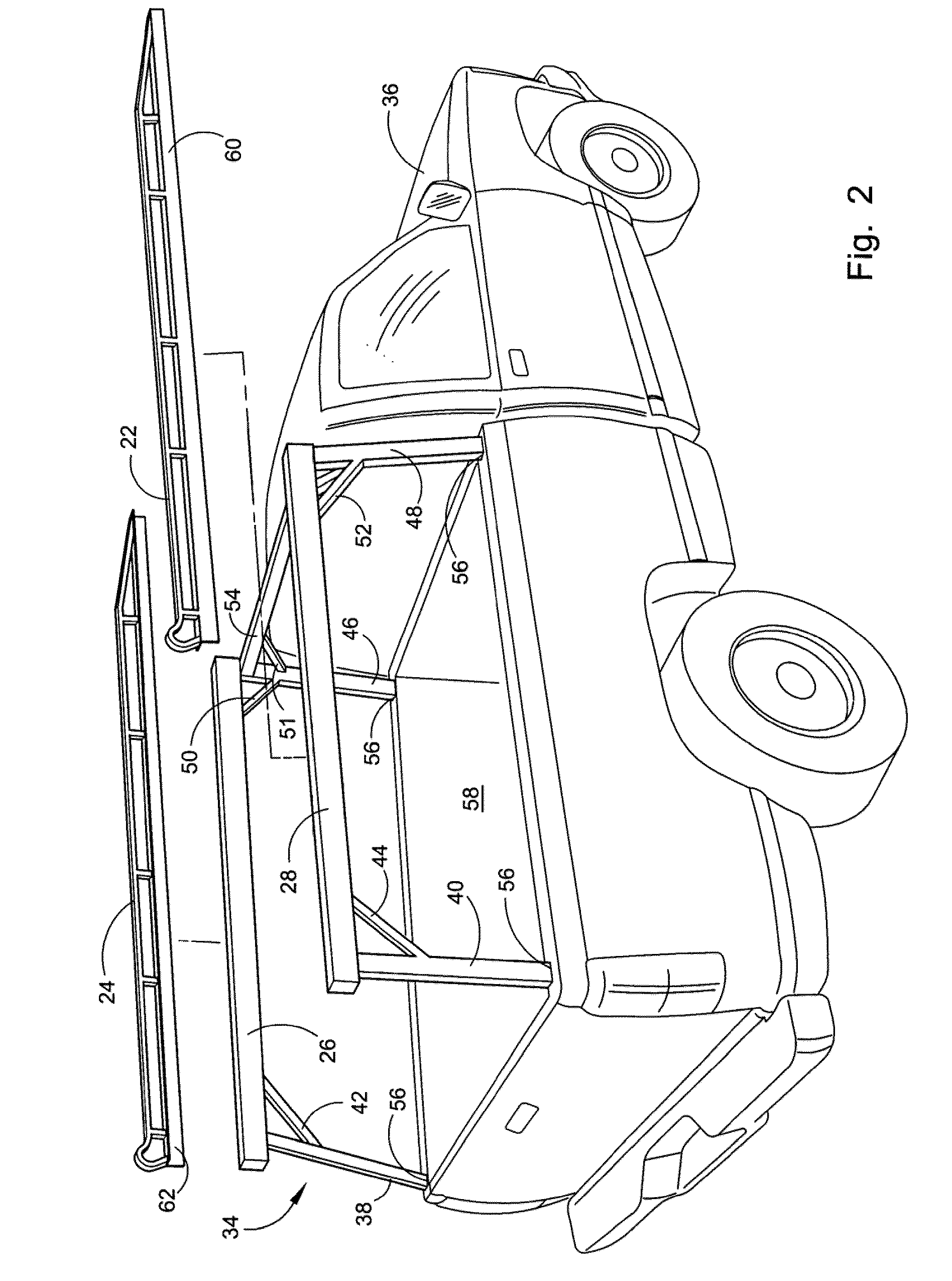
[0076]Referring now to the drawings, wherein similar parts of the retractable roof system truck shell 10 are identified by like reference numerals, there is seen in FIG. 1 a perspective view of the retractable roof system truck shell 10 installed on a quad-cab pick-up truck 12. The right side window panel 14, the rear window panel 16, the front window panel 17, the rear roof panel 18 and the forward roof panel 20 form the exterior shell of the retractable roof system truck shell. The optional lumber rack set members 22 and 24 are shown attached to the left track assembly 26 and the right track assembly 28, joined by three lumber rack crossbars 30. These lumber rack crossbars may be replaced by using padded load stabilizing bars or sport rack bars (see FIG. 18) which are adjustable in the fore and aft directions to accommodate loads of varying length. Arrow A indicates capability of the rear window panel 16 to rotate up, over, and atop the rear roof panel 18, and trigger-latch secure...


PUM

PropertyMeasurementUnit
areaaaaaaaaaaa
lengthaaaaaaaaaa
sizeaaaaaaaaaa

Abstract

The present invention is directed to a retractable roof system that provides slidable roof sections for vehicles and truck bed shells / caps, where the cargo area roof panels and rear window panel (hatch above tailgate) may be moved forward and above the seating area roof section, by means of a telescoping track system. Additionally, as applied to vehicles, the roof section above the seating areas may be moved rearward and above the cargo area roof section. The retractable roof system truck bed shell / cap assembly will come in segments that can be stored and shipped in a relatively small container. The shell / cap structure is composed of metal frame members and window panels. Right and left telescoping track assemblies are mounted on the metal frame members, with roof panels secured between them. Side and front window panels are attached to the exterior of the metal frame members to form the shell / cap walls. The rear window panel is attached to the rear roof panel by the means of a hinge and will pivot up onto the rear roof panel before the roof panels are moved forward and above the truck cab. An optional lumber / sport rack set may be mounted to the top of the left and right track assemblies.

Description

[0001]This patent application claims the benefit of, and is a continuation-in-part (CIP) of U.S. patent application Ser. No. 12 / 111,966 filed on Apr. 30, 2008.FIELD OF THE INVENTION[0002]This application relates to the general field of vehicle manufacturing and after-market parts. As applied to vehicles, the retractable roof system allows roof sections (described herein as roof panels) to be slidably retracted, to expose either the cargo bay, or the seating area. The vehicle design variation applies to sport utility vehicles (SUVs), vans, sport / station wagons, sedans, busses and boats, including commercial, military, recreational and rescue applications. The retractable roof system will allow the translation of a plurality of roof panels in both (fore and aft) directions, to allow passengers the option of stowing seating area roof panels atop the cargo area roof panels, and additionally, the option of stowing the cargo area roof panels (and hingeably attached rear window panel) atop...

Claims


Application Information

Patent Timeline
Patent Type & Authority Patents(United States)
IPC IPC(8): B60P7/02
CPCB60J1/1884B60J7/047Y10T29/49826
Inventor JOAB, JACOB J.
Owner JOAB JACOB J
Why Eureka
Try Eureka