Internal combustion engine with secondary air injection system

Inactive Publication Date: 2011-03-29
MANN HUMMEL GMBH
View PDF17 Cites 7 Cited by
  • Summary
  • Abstract
  • Description
  • Claims
  • Application Information

AI Technical Summary

Benefits of technology

[0005]It is therefore an object of the present invention to provide an internal combustion engine and a method for operating this internal combustion engine which ensure operation of the secondary air injection system even for diesel engines.
[0013]A further alternative possibility is to use electrical energy, i.e., an electric motor, to drive the intake air compressor. This has the advantage that the intake air compressor may be driven independently of the speed of the internal combustion engine and thus may boost the torque of the internal combustion engine over a very broad range. This intake air compressor also has an overpressure branch for collecting the overpressure, the overpressure then being able to be used to drive the secondary air system.
[0016]It is advantageous if the outlet of the secondary air turbine is also connected to the exhaust gas system of the diesel internal combustion engine, and a regulating system is provided which regulates the secondary air supply via the secondary air compressor outlet or via the secondary air turbine outlet or via both outlets simultaneously. Air quantity losses due to a decrease in one of the air flows through one of the two outlets may thus be avoided, and a large available air volume may be achieved for fresh air enrichment in the exhaust gas posttreatment system.
[0017]To achieve better efficiency, it is advantageous to provide a second secondary air system, the outlet of the first secondary air turbine being connected to the inlet of the second secondary air turbine and the outlet of the first secondary air compressor being connected to the exhaust gas posttreatment system. The fresh air exiting from the second secondary air compressor and the second secondary air turbine is also subsequently supplied to the exhaust gas system of the diesel internal combustion engine. The secondary air compressor of the second secondary air system is preferably connected via a filter to the environment. Furthermore, the large temperature drop at the turbine sides of both stages may be used, for example, in the exhaust gas recirculation cooling, in particular with plastic pipes, or also for other assemblies. In this way, the energy is optimally converted and the efficiency of the overall system is maximized.

Problems solved by technology

However, the pressure differential in the intake manifold before and after the throttle valve required for driving the turbine only arises in operating states with a closed or nearly closed throttle valve.

Method used


Image

  • Internal combustion engine with secondary air injection system
  • Internal combustion engine with secondary air injection system
  • Internal combustion engine with secondary air injection system

Examples


Embodiment Construction

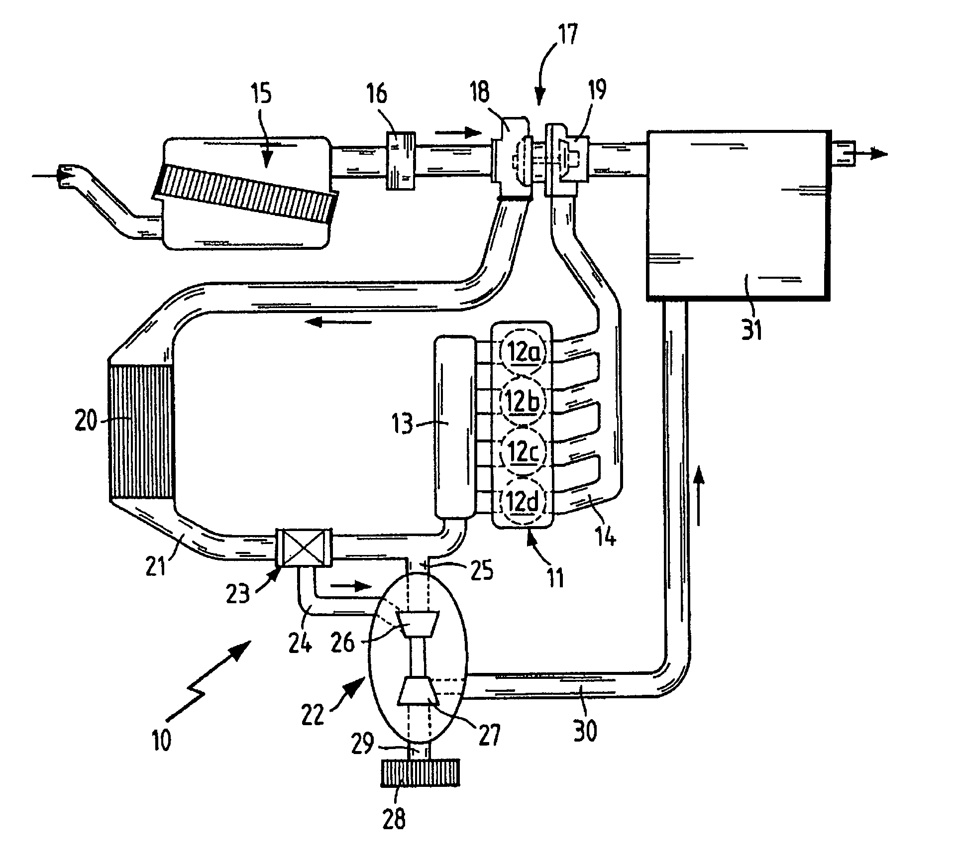
[0024]FIG. 1 shows a diesel internal combustion engine 10 comprising a motor 11 having four cylinders 12a through 12d. An intake manifold 13 leads to these four cylinders, while the exhaust gases are removed via an exhaust manifold 14. Fresh air is filtered via an air filter 15, conducted through a mass air flow meter 16 to determine the mass volume flow and guided to an intake air compressor 18 of an exhaust gas turbocharger 17. The intake air compressor 18 is coupled to an exhaust gas turbine 19, so that the passage of combustion exhaust gases from the exhaust gas manifold 14 out through the exhaust gas turbine 19 results in compression of the intake air in the intake air compressor 18. The compressed intake air is subsequently conducted through a charge air cooler 20 and an intake line 21 to the intake manifold 13.

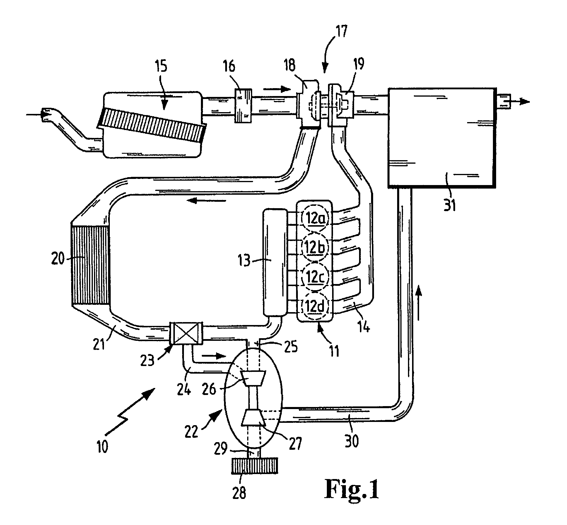
[0025]A secondary air system 22 is arranged to branch off from the intake line 21 at a point provided with a regulating valve 23. A secondary air turbine supply line 24...


PUM


Abstract

A method for operating a diesel internal combustion engine having a compressed air source, a diesel particulate filter situated in the exhaust gas system, and a secondary air line and secondary air compressor for introducing secondary air into the exhaust gas system of the internal combustion engine, in which the compressed air source is used to drive the secondary air compressor.

Description

BACKGROUND OF THE INVENTION[0001]The present invention relates to a method for operating an internal combustion engine, which has a secondary air line system for introducing secondary air into the exhaust system and to an internal combustion engine having a secondary air line system for introducing secondary air into the exhaust system.[0002]Secondary air injection systems are used for decreasing hydrocarbon (HC) and carbon monoxide (CO) emissions during the cold start of internal combustion engines. Fresh air is blown onto the exhaust gas side using this system, and thus HC and CO are afterburned. Simultaneously, the exhaust gas temperature increases, and the catalytic converter reaches its effective operating temperature sooner.[0003]A secondary air injection system of this general type is known, for example, from U.S. Pat. No. 6,094,909 (=WO 97 / 38212). The basic construction may be seen from FIG. 2. The secondary air is taken through a line 13 from the filtered air side of the in...

Claims


Application Information

Patent Timeline
Patent Type & Authority Patents(United States)
IPC IPC(8): F01N3/00
CPCF01N3/023F01N3/32F02B37/00F02B37/164F02D2009/0283Y02T10/144Y02T10/12
Inventor SCHICK, HEDWIGFISCHER, HELMUTHBAUMANN, JOHN
Owner MANN HUMMEL GMBH
Why Eureka
Try Eureka