
Modular lighting apparatus

a module and lighting technology, applied in the direction of lighting applications, coupling device connections, and with built-in power, etc., can solve the problems of discarded electronic ballast, the major cost of conventional cfls, etc., and achieve significant cost savings for the public, avoid waste and environmental contamination, and save money

Inactive Publication Date: 2011-03-15
VERILY PROD GRP LLC +1
View PDF20 Cites 80 Cited by
  • Summary
  • Abstract
  • Description
  • Claims
  • Application Information

AI Technical Summary

Benefits of technology

"The present invention is a modular lighting apparatus that includes a replaceable bulb assembly, an adapter, and a mechanical and electrical connector assembly that removably connects the bulb assembly to the adapter for use. The lighting apparatus can be used in existing household lighting fixtures and can be easily replaced when the bulb assembly reaches the end of its useful life. The lighting apparatus includes a variety of light-emitting components that can be used for different needs and can be adapted for use with existing lighting fixtures. The adapter also includes an integral photocell for automatic on / off control without increasing the overall height of the composite lighting apparatus. The technical effects of the present invention include significant cost savings, avoidance of waste and environmental contamination, and increased safety for use in small spaces."

Problems solved by technology

In particular, a major cost of conventional CFLs is the electronic ballast, which is discarded when the bulbs burn out even though the ballasts normally have much more life left in them.

Method used


Image

  • Modular lighting apparatus
  • Modular lighting apparatus
  • Modular lighting apparatus

Examples


Embodiment Construction

[0024]The present invention may be understood more readily by reference to the following detailed description of the invention taken in connection with the accompanying drawing figures, which form a part of this disclosure. It is to be understood that this invention is not limited to the specific devices, methods, conditions or parameters described and / or shown herein, and that the terminology used herein is for the purpose of describing particular embodiments by way of example only and is not intended to be limiting of the claimed invention. Also, as used in the specification including the appended claims, the singular forms “a,”“an,” and “the” include the plural, and reference to a particular numerical value includes at least that particular value, unless the context clearly dictates otherwise. Ranges may be expressed herein as from “about” or “approximately” one particular value and / or to “about” or “approximately” another particular value. When such a range is expressed, another...


PUM


Abstract

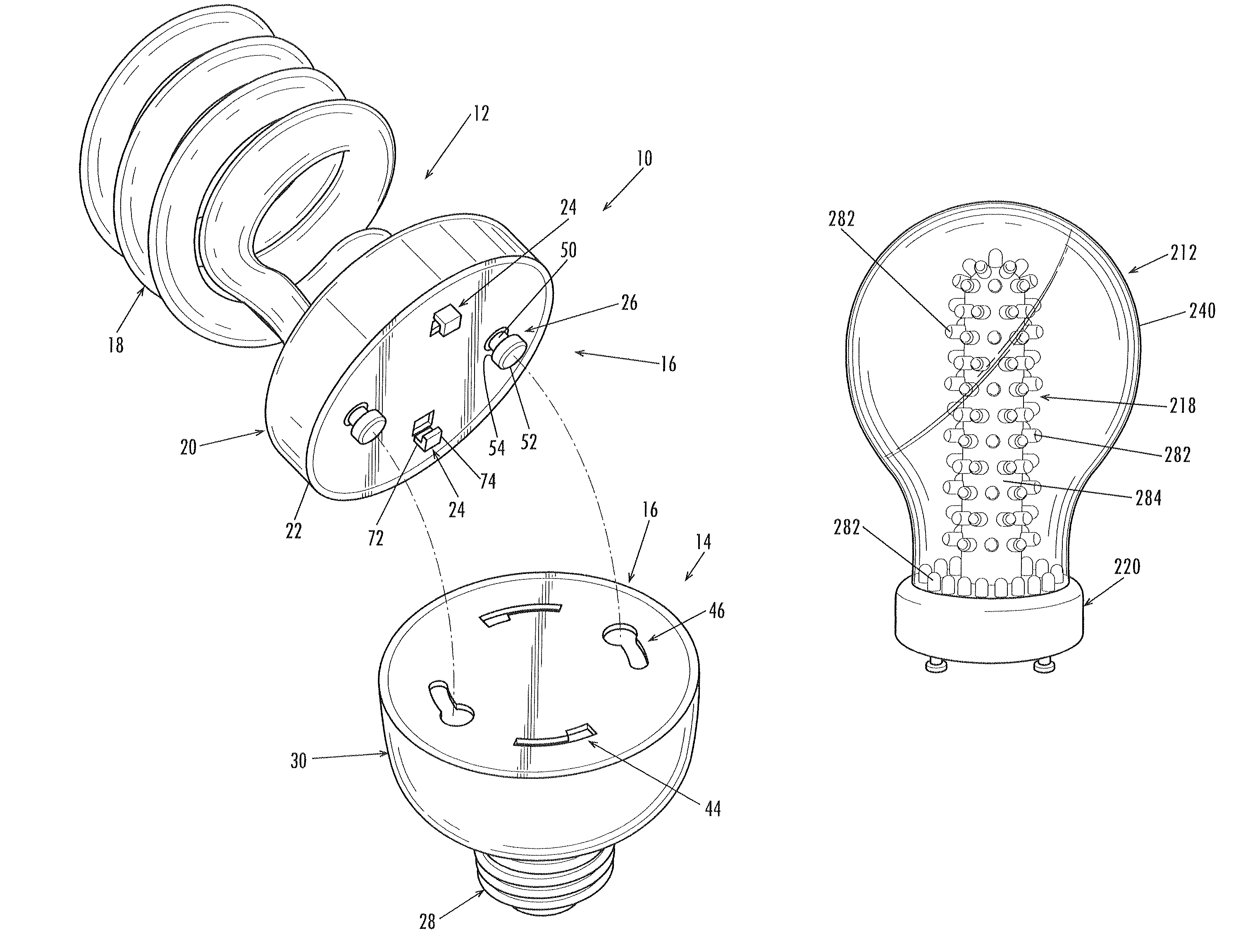
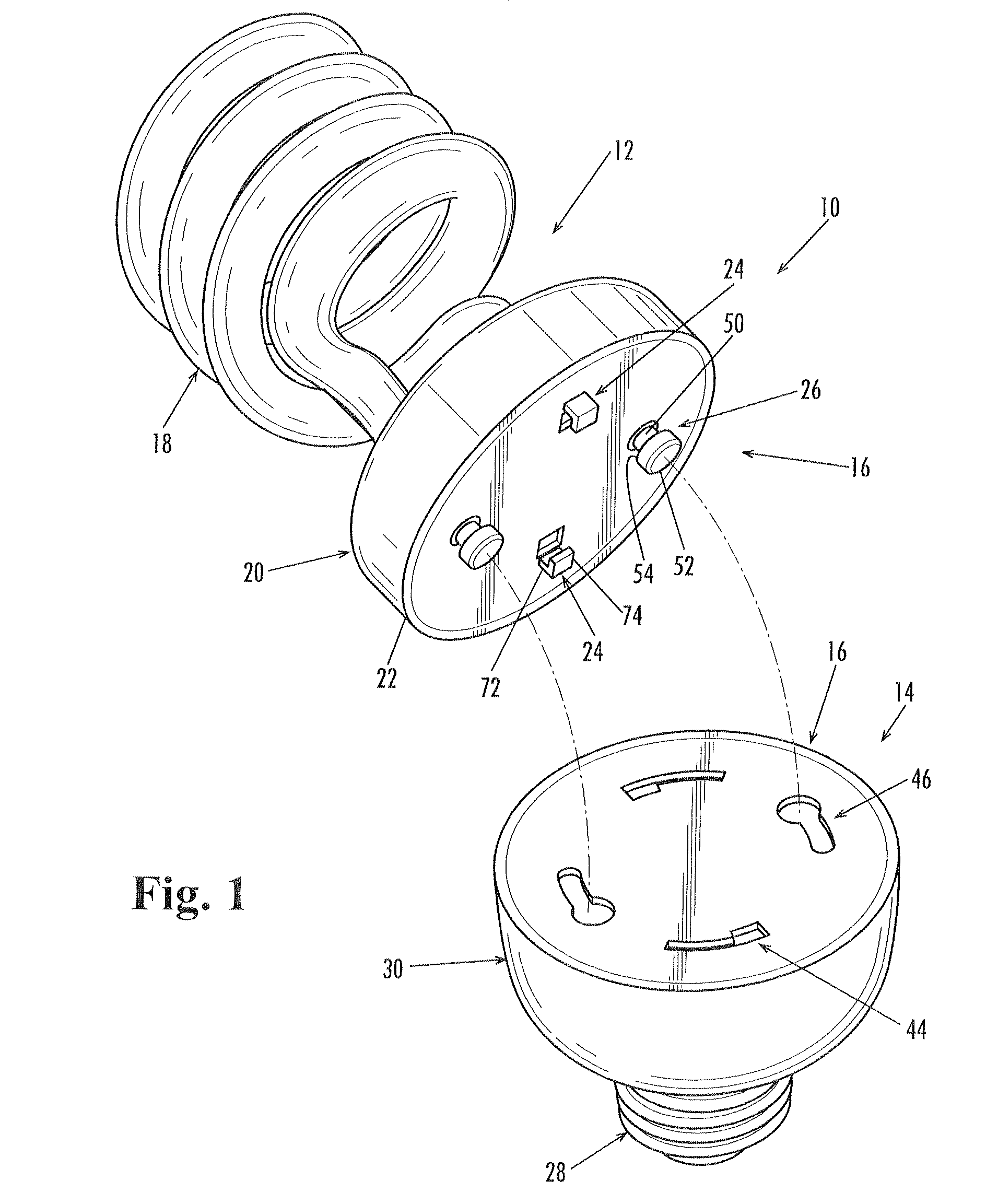
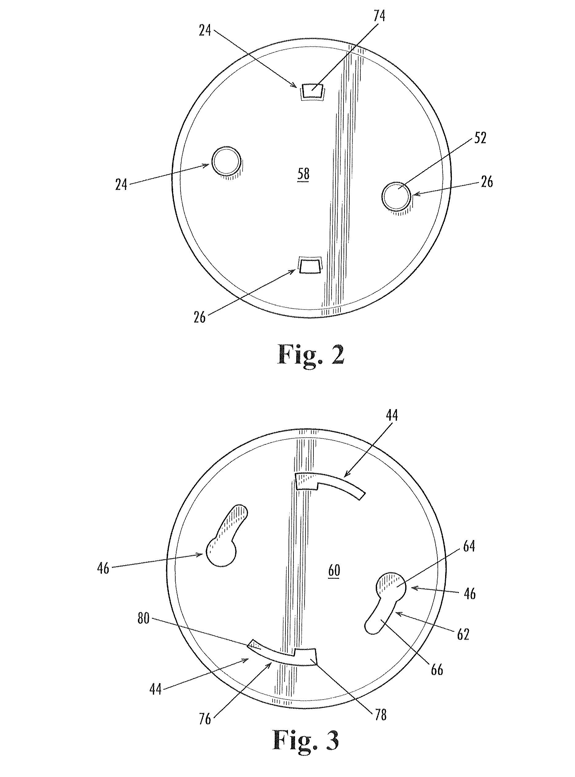
A modular lighting apparatus includes a replaceable bulb assembly, an adapter, and a mechanical and electrical connector assembly that removably connects the bulb assembly to the adapter for use. The bulb assembly includes a light-emitting component mounted to a body. In example embodiments the light-emitting component includes spiral-tube CFLs, low-profile transverse CFL tubes, and omni-directional LED arrays. The adapter includes a standard screw base mounted to a body that houses an electronic ballast. In this way, the bulb assembly can be removed from the adapter and replaced, while reusing the electronic ballast in the adapter. And the screw-base adapter allows the reuse of the electronic ballast in standard screw-socket household light fixtures. In addition, the reusable adapter base also may be provided with an integral photocell for light-based control of the lighting apparatus without increasing the overall height of the composite lighting apparatus.

Description

CROSS-REFERENCE TO RELATED APPLICATION[0001]This application claims the priority benefit of the U.S. Provisional Patent Application Ser. No. 61 / 003,675, filed Nov. 19, 2007; U.S. Provisional Patent Application Ser. No. 61 / 003,702, filed Nov. 19, 2007; and U.S. Provisional Patent Application Ser. No. 60 / 965,027, filed Aug. 16, 2007, the entire scope and content of all of which is hereby incorporated herein by reference for all purposes.FIELD OF THE INVENTION[0002]The present invention relates generally to lighting apparatus and, in particular, to replaceable light bulbs for use in screw-socket light fixtures.BACKGROUND OF THE INVENTION[0003]Conventional screw-base incandescent bulbs remain the primary source of household electrical illumination. Compact fluorescent lamps (CFLs) with screw bases have been developed for household use, and they are much more efficient than incandescent bulbs. But CFLs currently account for only about 5 percent of the market for household electrical illu...

Claims


Application Information

Patent Timeline
Patent Type & Authority Patents(United States)
IPC IPC(8): H01R33/06
CPCF21K9/135H01J5/60H01J61/327F21V19/04F21V3/00H01J5/54F21Y2101/02F21Y2103/02F21Y2103/025F21Y2111/002F21Y2111/004F21K9/232F21Y2115/10F21Y2103/30F21Y2103/37F21Y2107/10F21Y2107/20
Inventor SHANTHA, TOTADA R.SUNDHAR, SHAAM P.
Owner VERILY PROD GRP LLC
Learn More