Rotation angle transmitter and method of scanning a code disc of a rotation angle transmitter

a technology of rotation angle transmitter and code disc, which is applied in the field of optical rotation angle transmitter, can solve the problems of particularly low manufacturing expenditure and achieve the effect of low manufacturing expenditure and avoiding errors

Inactive Publication Date: 2011-03-08
TRW AUTOMOTIVE ELECTRONICS & COMPONENTS GMBH & CO KG
View PDF19 Cites 2 Cited by
  • Summary
  • Abstract
  • Description
  • Claims
  • Application Information

AI Technical Summary

Benefits of technology

[0009]According to the invention, this is achieved in an optical rotation angle transmitter comprising a code disc that has a digital coding and an analog coding. The digital coding has multiple tracks and is configured so as to be secure against error. A current angle interval can be determined from a plurality of possible angle intervals by means of the digital coding, and a precise angle position of the code disc can be determined within the current angle interval by means of the analog coding. Each of the tracks of the digital coding has a light sensor associated with it. In this way, a particularly low manufacturing expenditure results. Owing to the digital coding, secure against error, additional code tracks which serve for security are not necessary.
[0010]According to a preferred embodiment of the invention, a processing system is provided in which maximum or respectively minimum scanning values of the analog coding can be stored as interpolation reference. In this way, any measured value deviations which are due to changes, as caused by age, in the components of the rotation angle transmitter can be prevented.
[0011]In an advantageous aspect of the invention, provision is made that the digital code tracks partly overlap following phase shifts. The number of code tracks required can thus be further reduced, resulting in reduced structural dimensions.

Problems solved by technology

In this way, a particularly low manufacturing expenditure results.

Method used


Image

  • Rotation angle transmitter and method of scanning a code disc of a rotation angle transmitter
  • Rotation angle transmitter and method of scanning a code disc of a rotation angle transmitter
  • Rotation angle transmitter and method of scanning a code disc of a rotation angle transmitter

Examples


Embodiment Construction

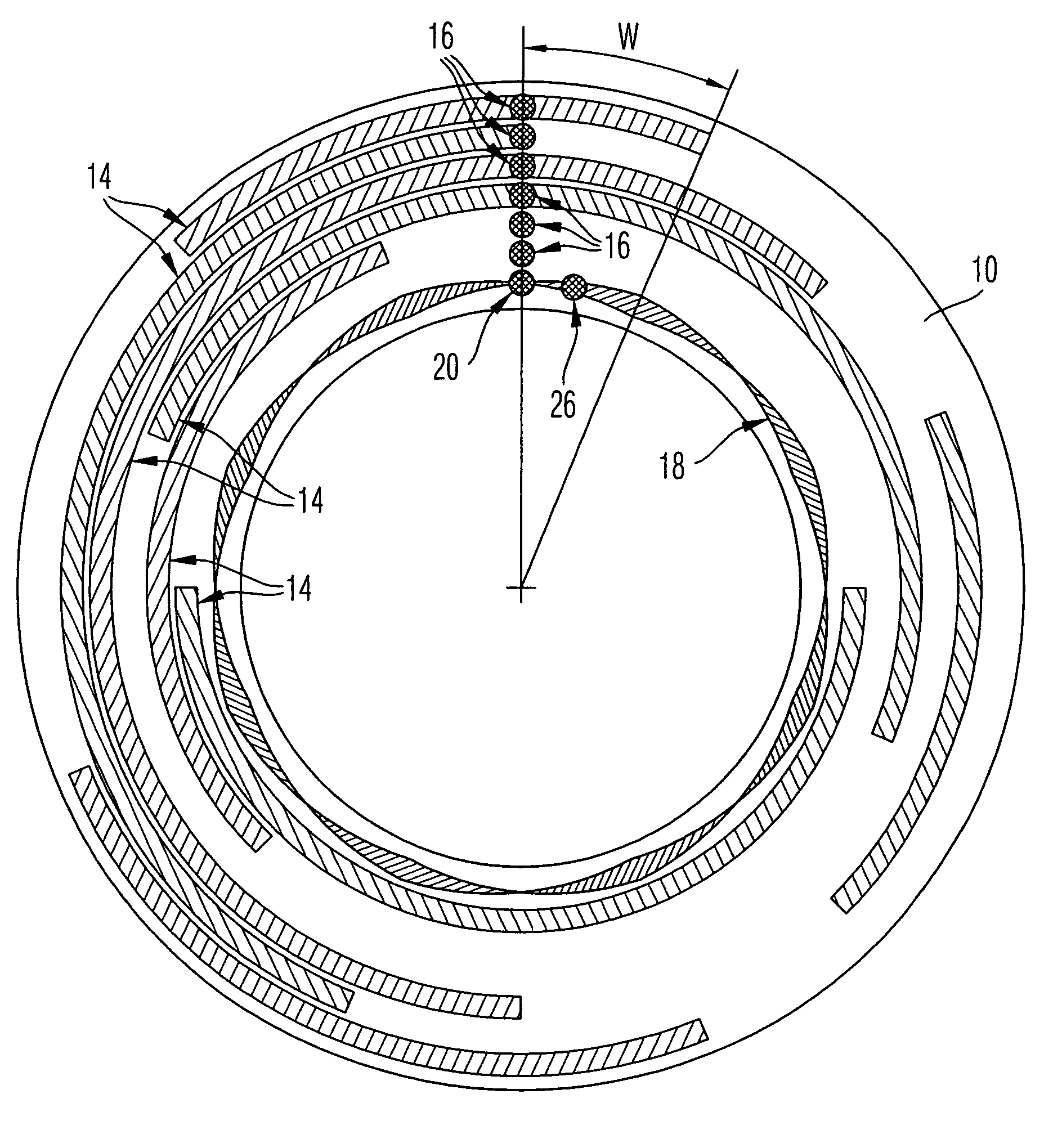
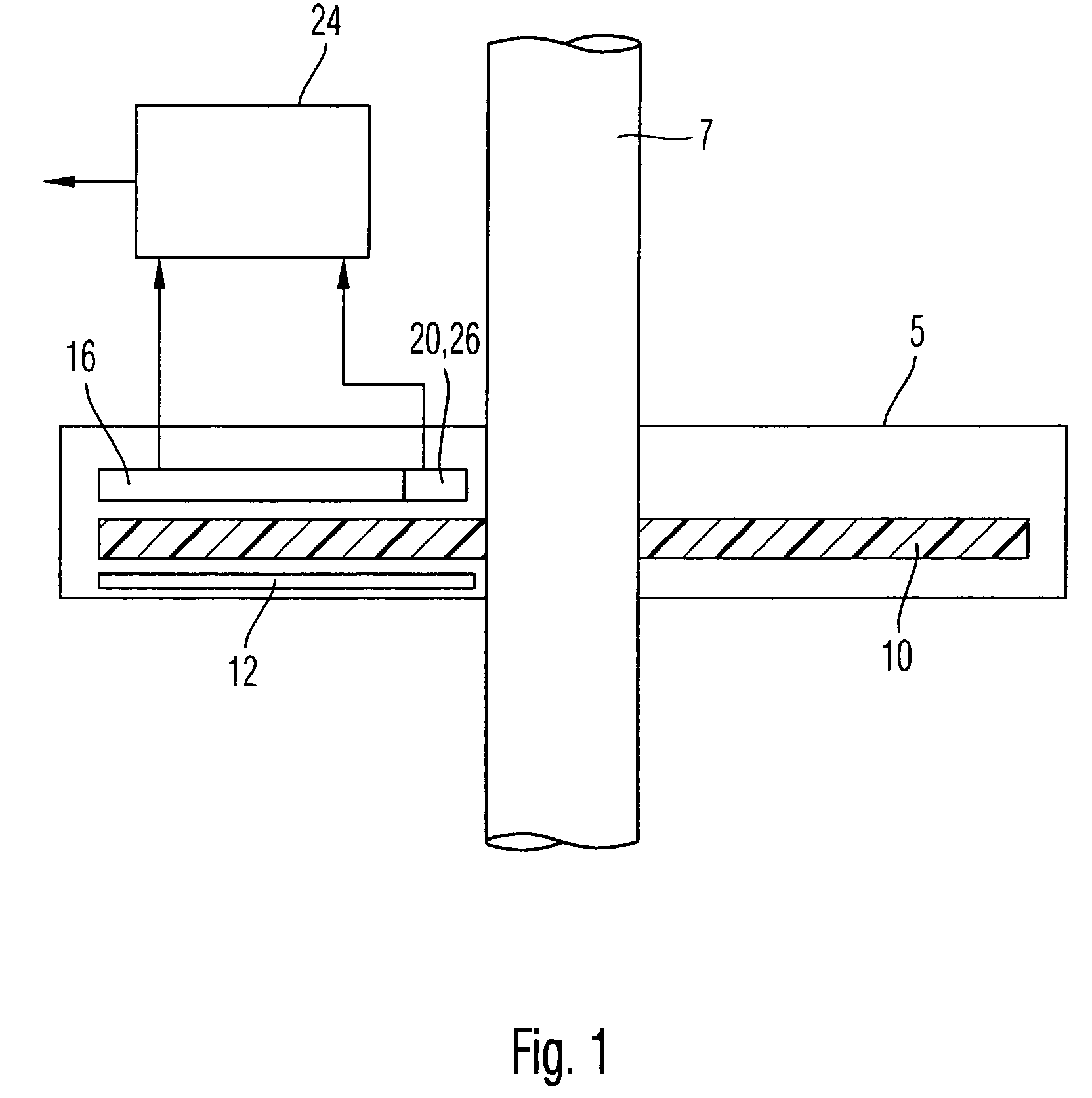
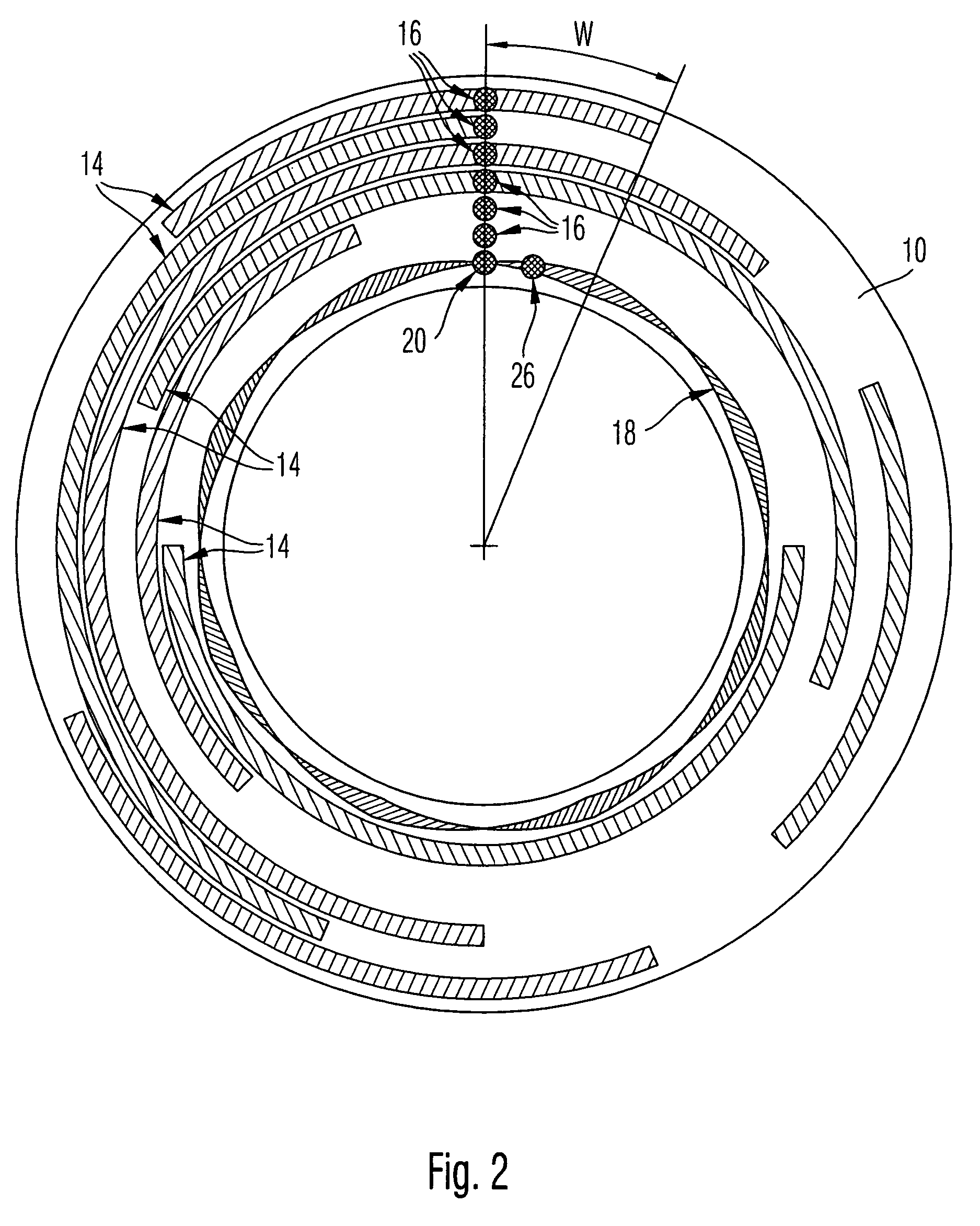
[0018]In FIG. 1 a rotation angle transmitter 5 is shown, which is part of a steering angle sensor. The steering angle sensor serves to determine the angle position of a diagrammatically indicated steering shaft 7.

[0019]The rotation angle transmitter has a code disc 10 (see also FIG. 2), which is connected with the steering shaft 7 so as to rotate jointly therewith. The code disc 10 consists of plastic and is constructed so as to be transparent in the example embodiment shown. On the code disc, different code tracks are arranged, which make possible two kinds of angle determination, namely on the one hand a differentiation of various angle intervals W and on the other hand an angle determination within one of these angle intervals (see also FIG. 3). The code tracks are illuminated by a diagrammatically shown light source 12.

[0020]For differentiation between various angle intervals W, several series of digital code tracks 14 are provided. “Digital” means here that each code track 14 p...


PUM

PropertyMeasurementUnit
current angleaaaaaaaaaa
rotation angleaaaaaaaaaa
phase shiftsaaaaaaaaaa

Abstract

An optical rotation angle transmitter includes a code disc that has a digital coding and an analog coding. The digital coding has multiple tracks and is configured so as to be secure against error. A current angle interval can be determined from a plurality of possible angle intervals by means of the digital coding, and a precise angle position of the code disc can be determined within the current angle interval by means of the analog coding. Each of the tracks of the digital coding has a light sensor associated with it. Further provided is a method of scanning a code disc of a rotation angle transmitter.

Description

TECHNICAL FIELD[0001]The invention relates to an optical rotation angle transmitter, in particular to a rotation angle transmitter as can be used in a steering angle sensor of a motor vehicle. The invention further relates to a method of scanning a code disc of a rotation angle transmitter.BACKGROUND OF THE INVENTION[0002]From the prior art, various absolutely operating optical angle transmitters are known, which are based on the transparent or reflecting scanning of a code disc with digital tracks (see for example DE 198 55 064 and DE 199 44 005). Such rotation transmitters require log 2(N) code tracks for N angle positions which are to be represented. With limited structural space, the aperture width for each light sensor therefore decreases by 1 / log 2(N). At the same time, the aperture height decreases with 1 / N. The aperture area (and hence the amount of light available for each light sensor) therefore decreases with 1 / (N*log 2(N)), which greatly limits the accuracy able to be te...

Claims


Application Information

Patent Timeline
Patent Type & Authority Patents(United States)
IPC IPC(8): G01D5/34G11B3/70G01B11/26G01D5/244G01D5/249G01D5/347
CPCG01D5/24476
Inventor BACKES, ULRICH
Owner TRW AUTOMOTIVE ELECTRONICS & COMPONENTS GMBH & CO KG
Why Eureka
Try Eureka