
Injection device

a technology of injection device and drive spring, which is applied in the direction of intravenous device, automatic syringe, infusion needle, etc., can solve the problems of unsatisfactory device that is supposed to retract, failure of the release mechanism to operate, and difficulty in ensuring both the complete discharge of syringe contents and the reliable release of syringe from the drive spring. , to achieve the effect of reducing the volume of the reservoir, and reducing the component coun

Active Publication Date: 2011-03-08
CILAG GMBH INT
View PDF179 Cites 132 Cited by
  • Summary
  • Abstract
  • Description
  • Claims
  • Application Information

AI Technical Summary

Benefits of technology

[0011]a highly viscous fluid damping the movement of the first component relative to the second, so that the release of the syringe is delayed after the activation of the decoupling mechanism to allow the remaining contents of the syringe to be discharged before the syringe is released.
[0012]The delay between the activation of the decoupling mechanism and the activation of the release mechanism is used to compensate for any stacking of tolerances. Although triggering of the decoupling mechanism can be designed to occur before the contents of the syringe are fully discharged, the delay is so chosen that, for all variations within the intended tolerances of the components, release of the syringe will not occur until after its contents have been fully discharged. It thus becomes possible to ensure that the syringe contents have been discharged before it is retracted, without having to comply with unrealistically fine tolerances.
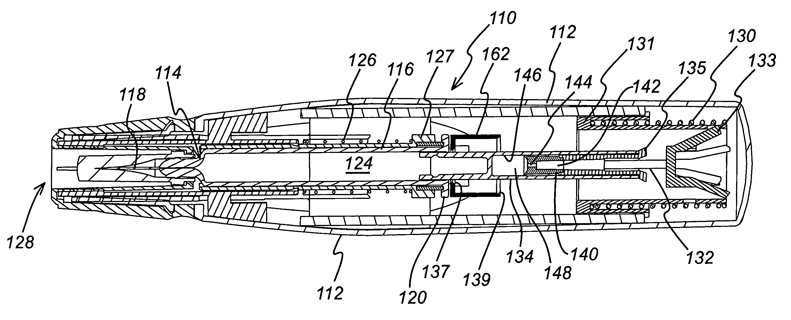
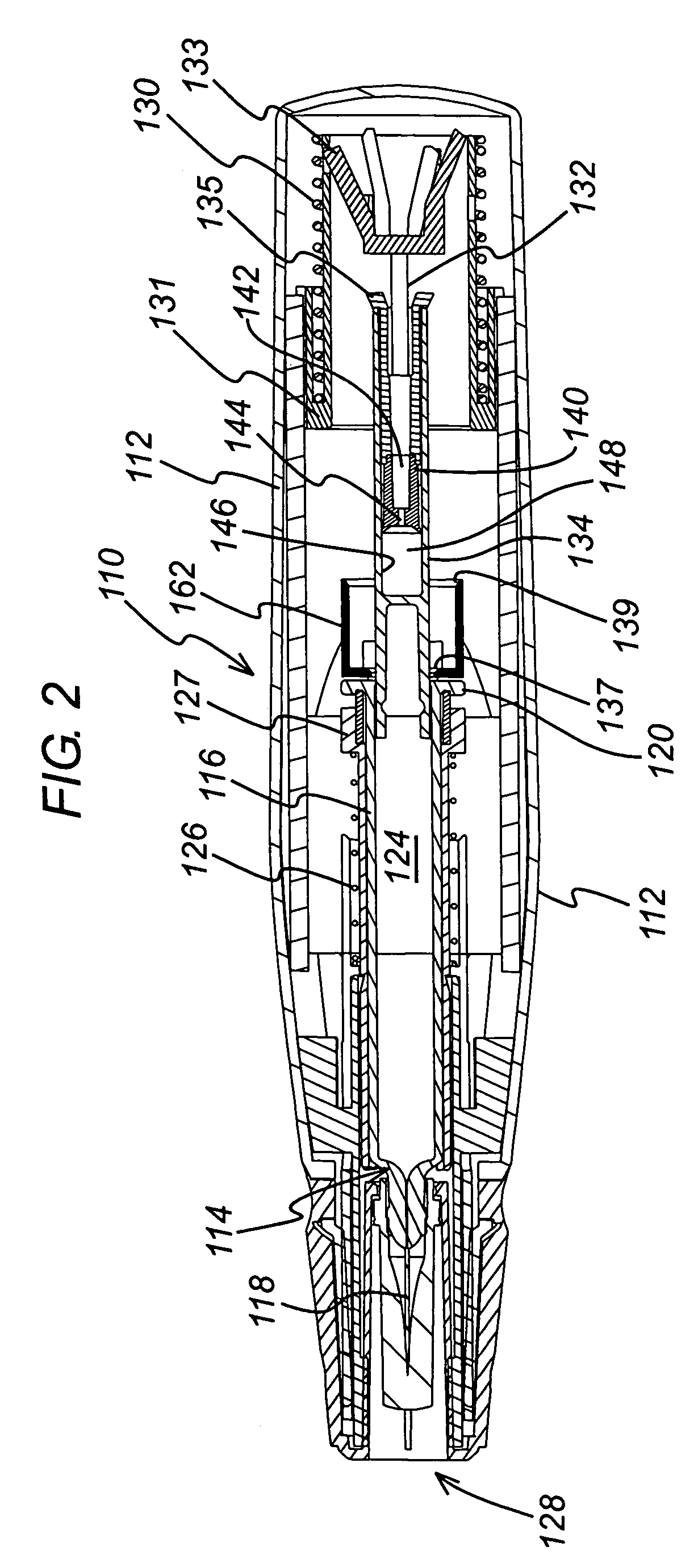
[0016]To reduce the component count and ensure the injection device remains compact, the first and second components of the device may be constituted by first and second elements of the drive, of which the first is acted upon by the actuator and the second acts upon the syringe, the first drive element being capable of movement relative to the second when the former is acted upon by the actuator and the latter is restrained by the syringe. As will be recognised, the relative movement of the first and second drive elements that is damped by the highly viscous fluid, is driven by the actuator. Use of the actuator in this way keeps down the component count.
[0017]A reservoir for the highly viscous fluid may be defined in part by the first drive element and in part by the second drive element, the volume of the reservoir tending to decrease as the first drive element moves relative to the second when acted upon by the actuator, the reservoir containing the highly viscous fluid and having a vent through which the fluid escapes as the volume of the reservoir decreases. This probably provides the simplest and most compact realisation of the fluid damping mechanism using a highly viscous fluid.
[0029]To reduce further the possibility of simulated wet injections or the impression that the syringe contents may have leaked within the device, the vent may be in communication with a collection chamber defined by one drive element, within which the escaped fluid is collected. In this case, for simplicity of manufacture, it is preferred that one drive element include a stem and define the vent and the collection chamber and the other drive element include a blind bore that is open at one end to receive the stem and closed at the other, the bore and the stem thus defining the fluid reservoir. Again, for greater simplicity of manufacture by injection moulding, the collection chamber may be defined by a bore in the said one element, being open at one end and closed at the other but for the vent.

Problems solved by technology

However, problems have arisen in devices such as these that make it difficult to ensure both complete discharge of the syringe contents and reliable release of the syringe from the drive spring.
The consequence of underestimating the safety margin is that the release mechanism may fail to operate even once the syringe contents have been discharged, which is unsatisfactory in a device that is supposed to retract automatically, particularly for self-administered drugs.
On the other hand, overestimating the safety margin may mean that some of the syringe contents are discharged after the syringe has retracted, which results firstly in a short dose and secondly in what may be termed a “wet” injection.
Wet injections are undesirable for the squeamish, particularly in connection with self-administered drugs.
0325596 make use of a fluid-damped delay mechanism that is particularly effective in ensuring complete discharge of the syringe contents, but creates problems of its own.
Firstly, the use of a fluid-damped delay mechanism requires the creation of a fluid-tight reservoir.
Secondly, it is undesirable for the fluid to leak out of its reservoir even when the device has been actuated, because that could give rise to a simulated wet injection, or to the impression that the syringe contents may have leaked within the device.
Again, fine tolerances or seals are called for, which pushes up the price of manufacture.

Method used


Image

  • Injection device
  • Injection device
  • Injection device

Examples


Embodiment Construction

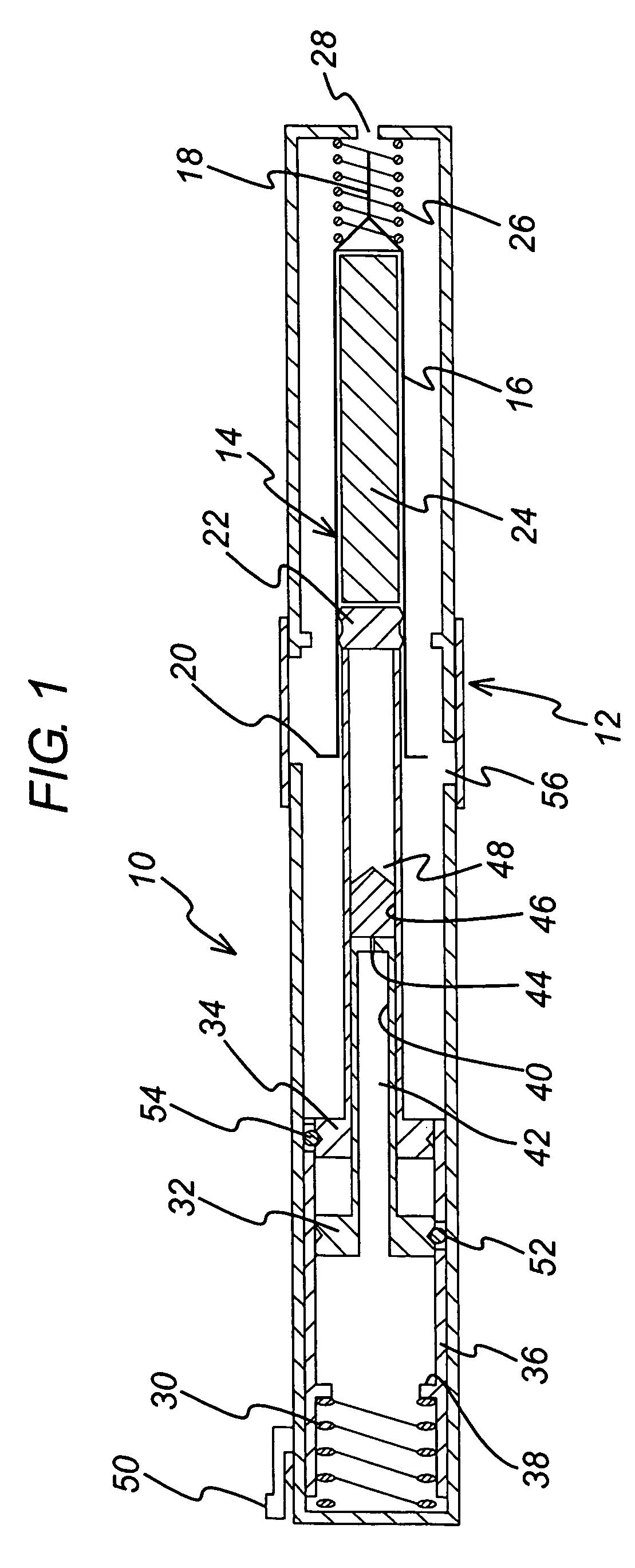
[0039]FIG. 1 shows an injection device 10 in which a housing 12 contains a hypodermic syringe 14. The syringe 14 is of conventional type, including a syringe body 16 terminating at one end in a hypodermic needle 18 and at the other in a flange 20, and a rubber bung 22 that constrains a drug 24 to be administered within the syringe body 16. The conventional plunger that would normally be connected to the bung 22 and used to discharge the contents of the syringe 14 manually has been removed and replaced with a drive element as will be described below. Whilst the syringe illustrated is of hypodermic type, this need not necessarily be so. Transcutaneous or ballistic dermal and subcutaneous syringes may also be used with the injection device of the present invention. Generally, the syringe must include a discharge nozzle, which in a hypodermic syringe is the needle 18. As illustrated, the housing includes a return spring 26 that biases the syringe 14 from an extended position in which th...


PUM


Abstract

An injection device (10; 110, 210) is described of the type that receives a syringe, extends it, discharges its contents and then retracts it automatically. The injection device makes use of a fluid-damped delay mechanism.

Description

BACKGROUND TECHNOLOGY[0001]The present invention relates to an injection device of the type that receives a syringe, extends it, discharges its contents and then retracts it automatically. Devices of this general description are shown in WO 95 / 35126 and EP-A-0 516 473 and tend to employ a drive spring and some form of release mechanism that releases the syringe from the influence of the drive spring once its contents are supposed to have been discharged, to allow it to be retracted by a return spring.[0002]However, problems have arisen in devices such as these that make it difficult to ensure both complete discharge of the syringe contents and reliable release of the syringe from the drive spring. Because of the stack up of tolerances of the various components of the device, a certain margin of safety must be built into the activation of the release mechanism, to ensure that it is effective. The consequence of underestimating the safety margin is that the release mechanism may fail ...

Claims


Application Information

Patent Timeline
Patent Type & Authority Patents(United States)
IPC IPC(8): A61M5/20A61M5/32
CPCA61M5/2033A61M2005/2086A61M2005/206A61M5/326A61M5/20A61M5/315A61M5/32
Inventor HARRISON, NIGEL D.BRADY, MATTHEW J.JOHNSTON, DAVID M.BARROW-WILLIAMS, TIM
Owner CILAG GMBH INT
Learn More