Laser processing method and chip
a laser processing and chip technology, applied in glass making apparatus, manufacturing tools, welding/soldering/cutting articles, etc., can solve the problems of inability to accurately cut objects, etc., to prevent fractures, shorten the approach distance, and shorten the time
- Summary
- Abstract
- Description
- Claims
- Application Information
AI Technical Summary
Benefits of technology
Problems solved by technology
Method used
Image
Examples
first embodiment
[0105]As shown in FIGS. 14 and 15, an object to be processed 1 comprises a silicon wafer 1, and a functional device layer 16 which is formed on the front face 11a of the silicon wafer 11a while including a plurality of functional devices 15. The silicon wafer 11 has such a crystal orientation that fractures are easy to extend in a direction different from its thickness direction t. Specifically, the silicon wafer 11 is a crystal structure having a cleavage plane in a direction parallel to its thickness direction and tilted with respect to a plane including a line to cut 5 which will be explained later, while fractures are likely to extend in a direction along the cleavage plane. Here, the front face 11a of the silicon wafer 11 is a (111) surface.
[0106]A number of functional devices 15, examples of which include semiconductor operating layers formed by crystal growth, light-receiving devices such as photodiodes, light-emitting devices such as laser diodes, and circuit devices formed ...
second embodiment
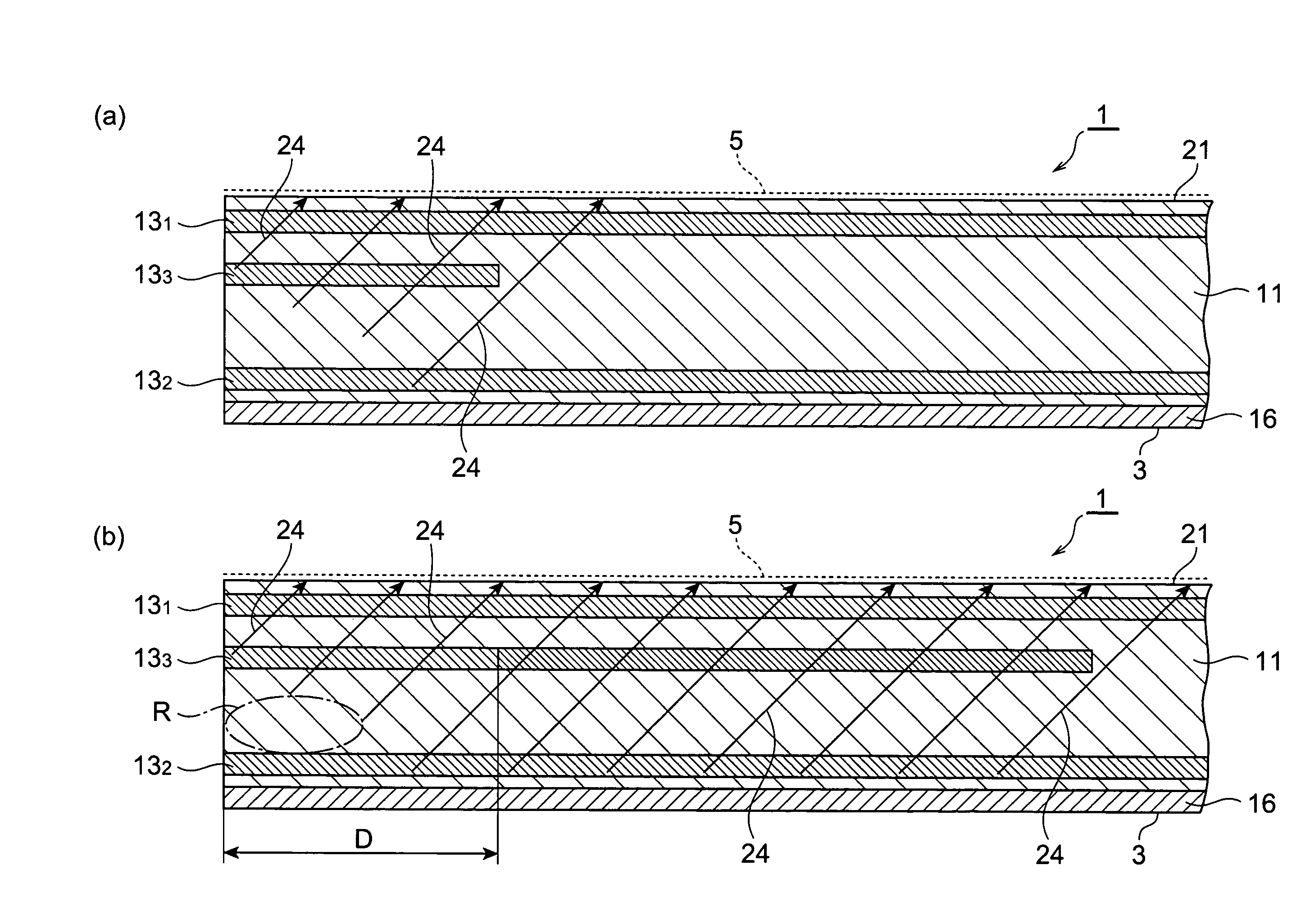
[0119]The laser processing method in accordance with a second embodiment of the present invention will now be explained. The laser processing method in accordance with the second embodiment differs from the laser processing method in accordance with the first embodiment shown in FIGS. 16 and 17 in that the modified region M4 is not formed. Specifically, the laser processing method in accordance with the second embodiment forms a modified region at a position deeper from the laser light entrance surface within the object along lines to cut, a modified region at a position shallower from the laser light entrance surface, and a modified region between these modified regions, and then cuts the object. This also has an effect similar to that mentioned above of preventing the end part of the cut section on the laser light entrance surface side from deviating greatly from the lines to cut when cutting the object as shown in FIG. 19(a).
third embodiment
[0120]The laser processing method in accordance with a third embodiment of the present invention will now be explained. The laser processing method in accordance with the third embodiment differs from the laser processing method in accordance with the first embodiment shown in FIGS. 16 and 17 in that a plurality of modified regions are sequentially formed from the opposite side of the laser light entrance surface to the laser light entrance surface side before forming the modified region M1. Specifically, for example, the laser processing method in accordance with the third embodiment uses an object to be processed having a thickness of 250 μm, sequentially forms 11 rows of modified regions from the position of 67 μm to the position of 23 μm, the 12th row of modified region at the position of 7 μm, the 13th row of modified region at the position of 13.5 μm, and the 14th row of modified region at the position of 10 μm while taking the laser light entrance surface as the origin (the p...
PUM
| Property | Measurement | Unit |
|---|---|---|
| size | aaaaa | aaaaa |
| transmittance | aaaaa | aaaaa |
| orientation | aaaaa | aaaaa |
Abstract
Description
Claims
Application Information
 - R&D
- Intellectual Property
- Life Sciences
- Materials
- Tech Scout
- Unparalleled Data Quality
- Higher Quality Content
- 60% Fewer Hallucinations
Browse by: Latest US Patents, China's latest patents, Technical Efficacy Thesaurus, Application Domain, Technology Topic, Popular Technical Reports.
© 2025 PatSnap. All rights reserved.Legal|Privacy policy|Modern Slavery Act Transparency Statement|Sitemap|About US| Contact US: help@patsnap.com


