
Validation method for embedded systems

a technology of embedded systems and validation methods, applied in adaptive control, process and machine control, instruments, etc., can solve problems such as insufficient, inability to build cases, and simulation under virtual constraints does not prevent testing in a practical environment, so as to save time and improve testing coverage

Inactive Publication Date: 2011-02-22
RENAULT SA
View PDF2 Cites 8 Cited by
  • Summary
  • Abstract
  • Description
  • Claims
  • Application Information

AI Technical Summary

Benefits of technology

The present invention provides an improved method for validating the design of embedded electrical systems, particularly safety critical systems used in vehicles. The method involves assigning user requests and system responses to a service, and automatically generating a skeleton validation environment for the service using a behavioral automata. The skeleton is recorded in a computer-readable memory device for use by a design validation tool. The method allows for the simulation of the test environment and the model of the service under test, saving time in the system design and development process and improving testing coverage and quality. The model of user request and system response accuracy can be predefined, and the method can be used for multiple services sharing at least one user request. The method can also include injecting faults for all replicated objects in a fault tolerant system and substituting models of the service with their software and hardware implementations. The invention provides a computer program and a design tool adapted for the validation of embedded electrical systems.

Problems solved by technology

However, for complex systems, it became quickly clear that this was not enough and design tools became executable tools allowing simulation.
Of course, simulation under virtual constraints does not prevent testing in a practical environment and the traceability from early requirements to an executable model and then test cases was not built in.
At this step however, which represents the current state of the art, the link between requirements, models and tests is not formal and has to be maintained manually.
Approaches like Universal Modeling Language (UML) make an attempt to capture the different process steps (requirements modeling and testing), but the UML formalism is too vague to support really more than an informal link between the different design steps.
In the case of manually generated tests, the state of the art consists in specifying test vectors that can be executed when the component under test has been set in a proper initial state, something which may be very difficult to reach for black box testing of a series electronic control unit (ECU).
It should be noted that for domains where the hardware design is very optimized, black box testing of series components is always necessary as the embedding of a real upper tester is too expensive.
Also, once a model is designed, a function may be distributed and then comes the challenge of providing unitary testing for each distributed piece of function; especially when the different pieces have to be developed by different suppliers.
This is an open issue.
This means that real debugging starts when the hardware design is frozen, a hardly efficient process.
At this stage again, no standard and determinist approach is available.
It is a disadvantage of U.S. Pat. No. 5,394,347 that the technology used does not distinguish between user requests and system responses, because it is then necessary to keep track of at least a “Variable Stack” and “Model Stack”.
Furthermore, this also means that in U.S. Pat. No. 5,394,347 it is only possible to validate the correct implementation of a specification and it is not possible to validate the specification itself.
This mechanism is not sufficient for the simulation of signal processing.

Method used


Image

  • Validation method for embedded systems
  • Validation method for embedded systems
  • Validation method for embedded systems

Examples


Embodiment Construction

[0049]An electronic system is made of Electronic Control Units (ECU), which may or may not be networked through communication busses, sensors, actuators, and electrical devices providing power to the different system components for example wiring, connectors, relays, fuses, battery and alternator.

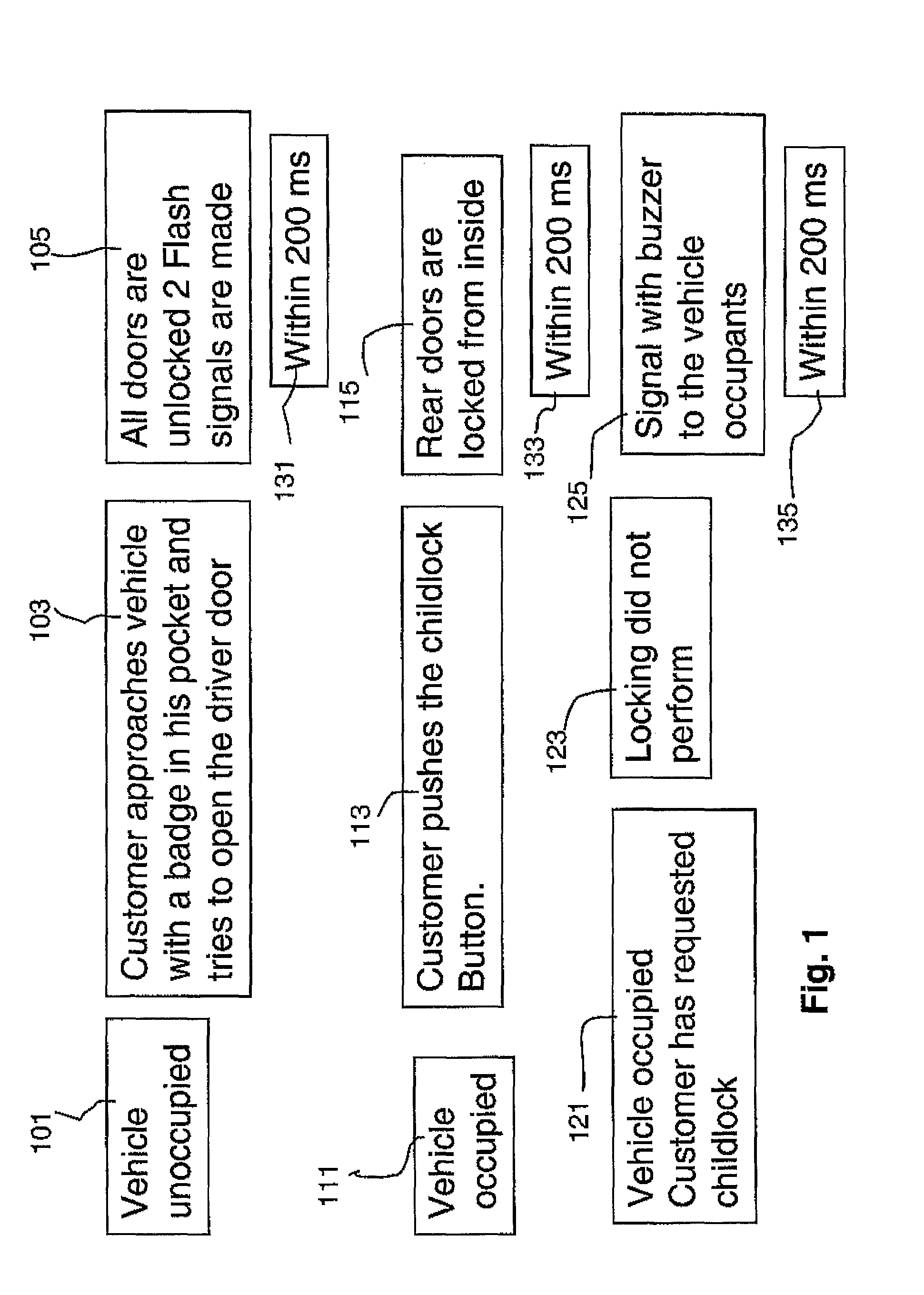
[0050]An electronic system implements services to a customer, be the customer a worker in a plant, a car driver, a garage mechanic or an engineer. For instance, in the case where the electronic system under discussion is embedded in a car, the systems as discussed in our invention may implement services like climate, car motion, or door locking.

[0051]As an electronic system may implement many services, it may in those cases be refined as a set of subsystems, each subsystem achieving a specific set of services. In the description, we will not need to consider such decomposition and will simply consider a system and one or several services implemented by that system. Implicitly, considering a...


PUM


Abstract

A method of designing a validation environment for a service implemented by an embedded electrical system. In the method one or more user requests and system responses are assigned. Next, a behavioral automata is assigned to the service, which fixes the allowed sequencing of the user requests and system responses. Then, a skeleton validation environment is automatically generated for the service. The skeleton validation environment includes testing automata produced from a traversal of the behavioral automata, a model of initial conditions, models of user requests, models of system response accuracy, an environmental model, and the dataflow and control flow assembling these models together. The skeleton validation environment covers all user requests and resultant system responses of the service. The skeleton validation environment is then recorded in a computer readable memory device for use by a design validation tool.

Description

FIELD OF THE INVENTION[0001]The present invention relates to the validation of system design and in particular to the design of a validation method for an embedded electrical system.BACKGROUND TO THE INVENTION[0002]Different tools and methods have been developed for systems design and testing. During the 1980's, structuring tools were developed allowing a system designer to specify the environment of his system and then, following a hierarchical approach, to specify the expected behavior of each part of the system. The structured analysis method is a good illustration of this first period.[0003]However, for complex systems, it became quickly clear that this was not enough and design tools became executable tools allowing simulation. During this paradigm shift however, the link between early system requirements and system executable specification was not preserved at first. Of course, simulation under virtual constraints does not prevent testing in a practical environment and the tra...

Claims


Application Information

Patent Timeline
Patent Type & Authority Patents(United States)
IPC IPC(8): G06G7/62G06F17/50
CPCB33Y50/00G06F30/20
Inventor BOUTIN, SAMUEL
Owner RENAULT SA
Learn More