Active radio tag, security management system, and security management method
a technology of security management system and active radio tag, applied in the field of active radio tag, security management system, security management method, can solve problems such as security problems, and achieve the effect of improving the security of a combined media operation
- Summary
- Abstract
- Description
- Claims
- Application Information
AI Technical Summary
Benefits of technology
Problems solved by technology
Method used
Image
Examples
first embodiment
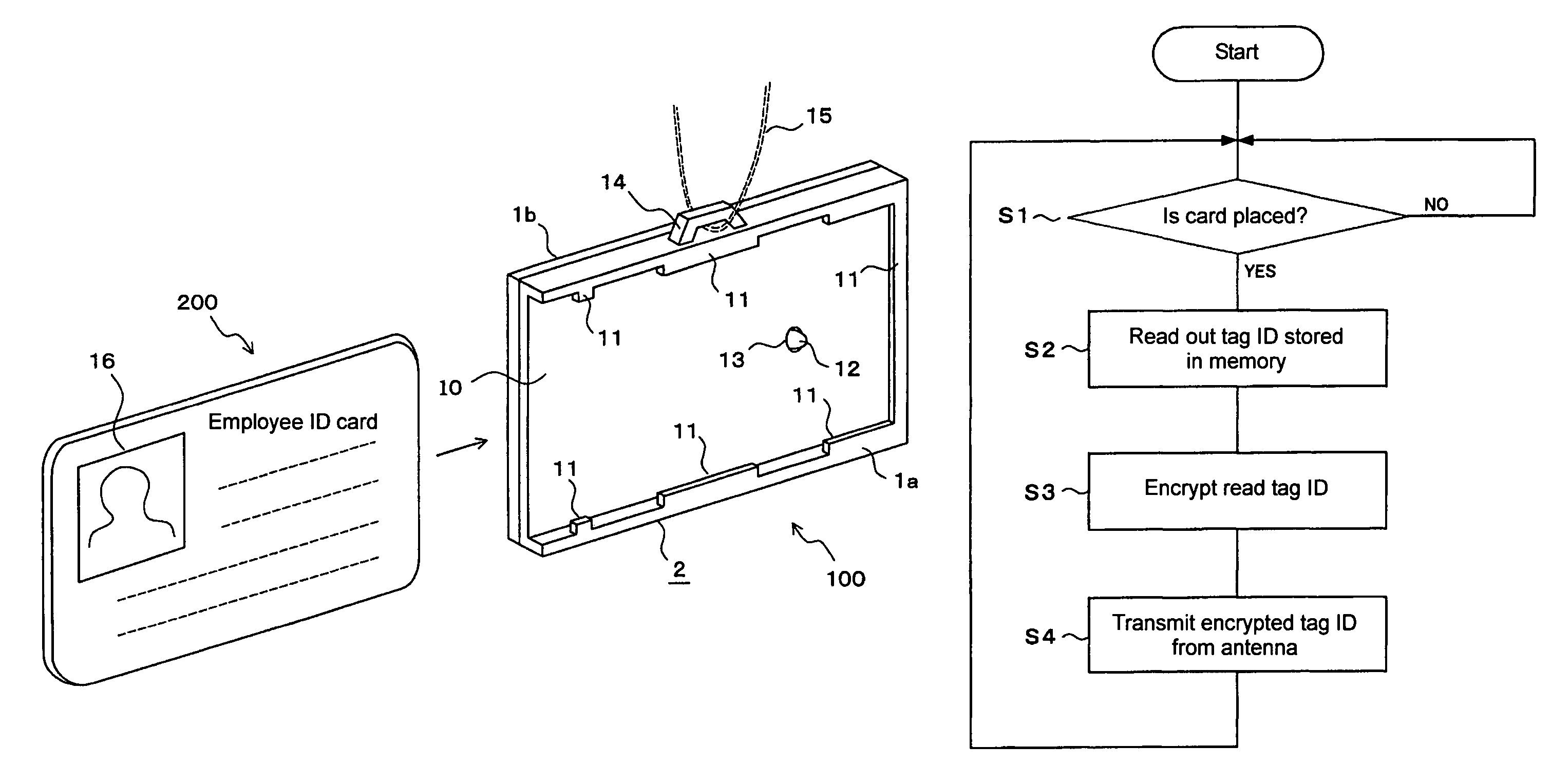
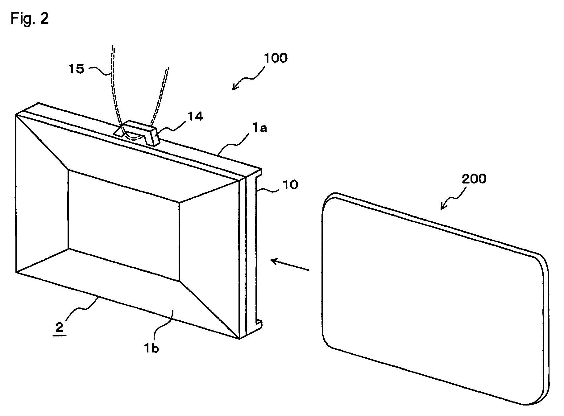
[0053]FIGS. 2 to 7 show the present invention. FIG. 2 is an external view of a radio tag 100 as seen from the back side thereof. The radio tag 100 includes a resin case 1a and a resin cover 1b which covers the case 1a. By the case 1a and the cover 1b, a card holder 2 is composed. On a top face of the case 1a is integrally formed a cord-threading section 14 for threading a cord 15. The cord 15 is used to hang the card holder 2 from the user's neck. On the front side of the case 1a is provided a card placement section 10 for placing a card 200. As such, since the radio tag 100 also serves as a card holder, two storage media, i.e., a tag and a card, can be physically integrated, providing convenience in handling.
[0054]FIG. 3A is a top view of the radio tag 100 and FIG. 3B is a front view of the radio tag 100 as seen from the back side (the lower side in FIG. 3A) of the case 1a with the cover 1b being removed. As shown in FIG. 3B, a board accommodation section 5 composed of surrounding ...
second embodiment
[0066]FIGS. 8 to 13 show the present invention. FIG. 8 is an external view of a radio tag 100 as seen from the back side thereof. In FIG. 8, the same parts as those in FIG. 2 are denoted by the same reference numerals. In FIG. 8, in addition to the configuration in FIG. 2, an operation button 3 is integrally provided to a cover 1b. The operation button 3 is provided with resilience by a cut groove being provided in the periphery of the operation button 3. When the operation button 3 is pressed with a finger, the operation button 3 is pressed toward the inside of the cover 1b and thereby allows a button press detection switch 9, which will be described later, to operate. When the finger is released, the operation button 3 returns to its original state.
[0067]FIG. 9A is a top view of the radio tag 100 and FIG. 9B is a front view of the radio tag 100 as seen from the back side (the lower side in FIG. 9A) of a case 1a with the cover 1b being removed. In FIG. 9, the same parts as those in...
third embodiment
[0078]FIGS. 14 to 17 show the present invention. FIG. 14 is an external view of a radio tag 100 as seen from the back side thereof. In FIG. 14, the same parts as those in FIG. 2 are denoted by the same reference numerals. In the present embodiment, a card 200 has a contact point 17. The contact point 17 is used to read card information stored in the card 200. Note that a card holder 2 has built therein a circuit board 6, a power supply section 7, and a circuit section 8 which are shown in FIG. 3B.
[0079]FIG. 15 is an external view of the radio tag 100 as seen from the front side thereof. In FIG. 15, the same parts as those in FIG. 4 are denoted by the same reference numerals. In FIG. 15, a contact 18 is provided instead of the card detection switch 12 in FIG. 4. The contact 18 is electrically connected to the circuit board.
[0080]FIG. 16 is a block diagram showing an electrical configuration of the radio tag 100. In FIG. 16, the same parts as those in FIG. 6 are denoted by the same re...
PUM
 Abstract
Description
Claims
Application Information
 - R&D
- Intellectual Property
- Life Sciences
- Materials
- Tech Scout
- Unparalleled Data Quality
- Higher Quality Content
- 60% Fewer Hallucinations
Browse by: Latest US Patents, China's latest patents, Technical Efficacy Thesaurus, Application Domain, Technology Topic, Popular Technical Reports.
© 2025 PatSnap. All rights reserved.Legal|Privacy policy|Modern Slavery Act Transparency Statement|Sitemap|About US| Contact US: help@patsnap.com


