
Fuel cell system and method for controlling operation of the fuel cell system

a fuel cell and system technology, applied in the direction of secondary cell servicing/maintenance, sustainable manufacturing/processing, final product manufacturing, etc., can solve the problems of difficult mechanically controlling the amount or concentration of fluid fuel to meet the magnitude of load, deterioration of operating efficiency and durability of the fuel cell system, and high cost of enlarging the capacity of the secondary cell, so as to achieve stable power to a load and low cost

Inactive Publication Date: 2011-02-08
SAMSUNG SDI CO LTD
View PDF22 Cites 13 Cited by
  • Summary
  • Abstract
  • Description
  • Claims
  • Application Information

AI Technical Summary

Benefits of technology

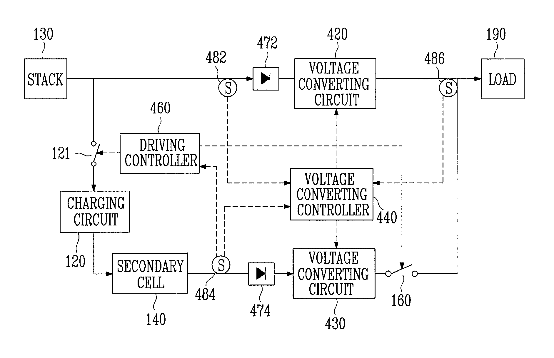
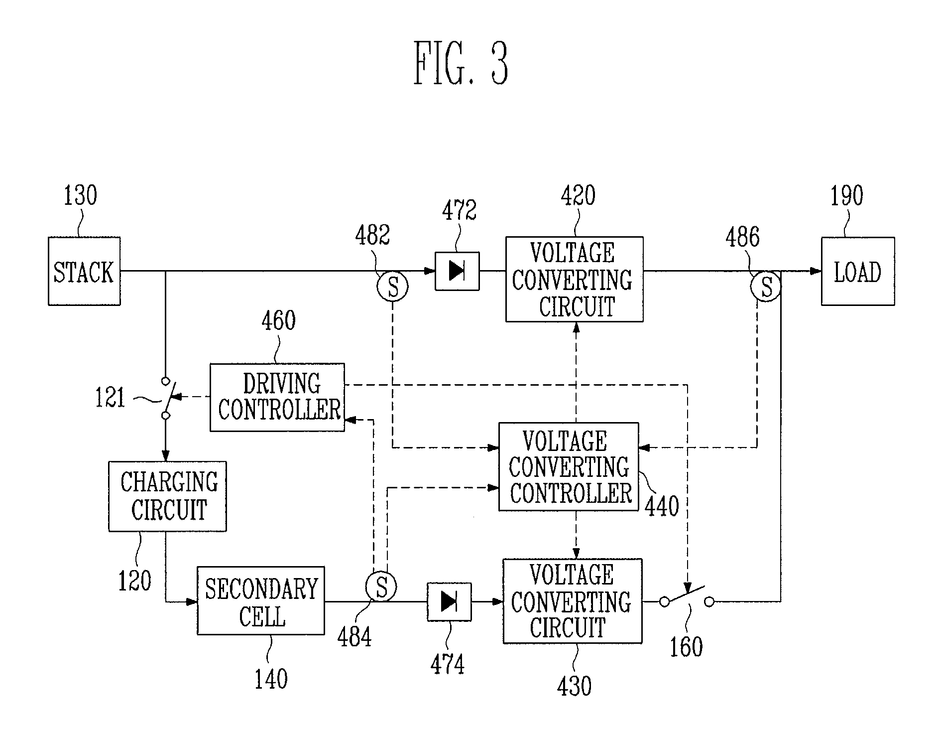
The present invention provides a fuel cell system and method for controlling its operation that can supply stable power to a load at a low cost. The system includes a fuel cell stack, a secondary cell, a stack voltage converting circuit, and a voltage converting controller. The method involves supplying power produced by the fuel cell stack and the secondary cell to the load simultaneously, controlling the conversion ratio of the stack voltage converting circuit to maintain the same voltage at the load node, and discharging the secondary cell while charging the load. The system can also include a secondary cell voltage converting circuit for converting the voltage discharged from the secondary cell and transferring it to the load. The invention can provide stable power to the load even with quick variations in the load demand.

Problems solved by technology

If the amount or the concentration of the fuel is controlled incorrectly, the operating efficiency and the durability of the fuel cell system are deteriorated.
But it is difficult to control mechanically the amount or the concentration of the fluid fuel to meet the magnitude of the load, which is electrically variable at high speed.
However, enlarging the capacity of the secondary cell is expensive and causes the cost to increase for the whole system.

Method used


Image

  • Fuel cell system and method for controlling operation of the fuel cell system
  • Fuel cell system and method for controlling operation of the fuel cell system
  • Fuel cell system and method for controlling operation of the fuel cell system

Examples


Embodiment Construction

[0023]In the following detailed description, certain exemplary embodiments of the present invention are shown and described, by way of illustration. As those skilled in the art would recognize, the described exemplary embodiments may be modified in various ways, all without departing from the spirit or scope of the present invention. Accordingly, the drawings and description are to be regarded as illustrative in nature, rather than restrictive.

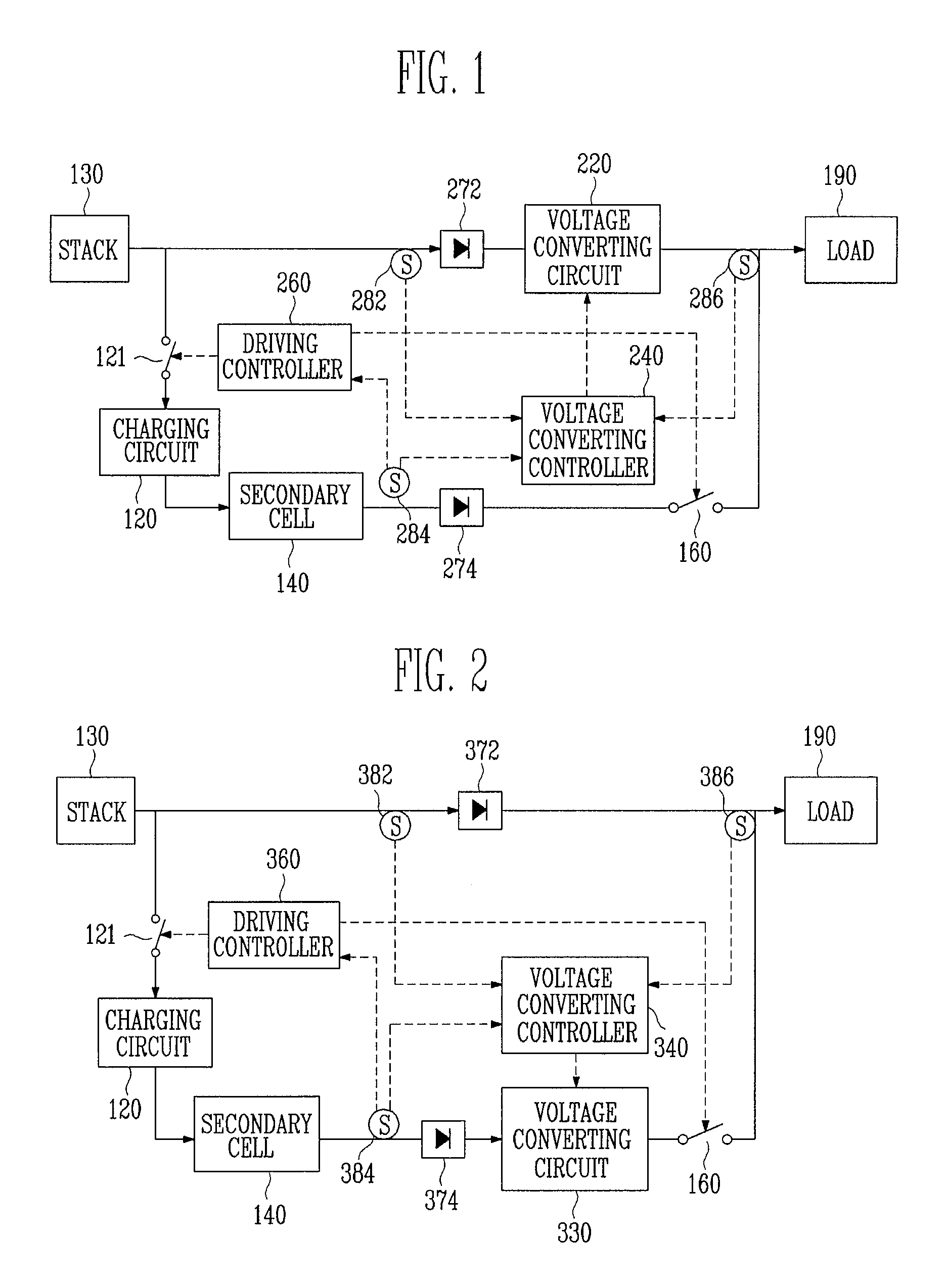
[0024]FIG. 1 is a schematic block diagram illustrating a fuel cell system with a stack voltage converter according to an embodiment of the present invention.

[0025]The fuel cell system illustrated in FIG. 1 includes a fuel cell stack 130 for producing power by an electrochemical reaction between fuel and oxidizer; a secondary cell 140 for storing power in the form of electric charges, and for discharging power; a stack voltage converting circuit 220 for converting voltage produced by the fuel cell stack and for transferring the converted voltag...


PUM

PropertyMeasurementUnit
voltageaaaaaaaaaa
voltageaaaaaaaaaa
voltageaaaaaaaaaa

Abstract

Fuel cell systems and methods for controlling fuel cell systems. In one embodiment, the method includes supplying power produced by operating the fuel cell stack in a maximum output mode to the load while concurrently charging the secondary cell with the produced power when an amount of charge of the secondary cell is smaller than a first standard value, supplying both power produced by operating the fuel cell stack in a stable output mode and the power discharged by the secondary cell to the load when the amount of charge of the secondary cell is larger than a second standard value, and maintaining an existing output mode among the output modes when the amount of charge of the secondary cell is larger than the first standard value and smaller than the second standard value.

Description

CROSS-REFERENCE TO RELATED APPLICATIONS[0001]This application claims priority to and the benefit of Korean Patent Application No. 10-2006-0113277, filed on Nov. 16, 2006, in the Korean Intellectual Property Office, the entire content of which is incorporated herein by reference.BACKGROUND[0002]The present invention relates to a system and method for controlling operation of a fuel cell system having a secondary cell, and more particularly to a system and method for maintaining stable output power of a fuel cell system.[0003]A fuel cell is a power generation system that generates electric energy by a well-balanced electrochemical reaction between hydrogen contained in a hydro-carbonaceous material such as methanol, ethanol and natural gas, and oxygen in the air.[0004]Fuel cells can be sorted according to the type of electrolyte used. Examples include a phosphoric acid fuel cell, a molten carbonate fuel cell, a solid oxide fuel cell, a polymer electrolyte fuel cell and an alkaline fue...

Claims


Application Information

Patent Timeline
Patent Type & Authority Patents(United States)
IPC IPC(8): H01M10/44H02J7/00
CPCH01M8/04559H01M8/04567H01M8/0488H01M8/04888H01M16/006H02J7/34H01M10/48H01M8/1011Y02E60/50H02J2001/004Y02E60/523H02J2300/30Y02P70/50Y02E60/10H01M8/04
Inventor KIM, DONG-RAKJEONG, SUNG-WON
Owner SAMSUNG SDI CO LTD
Learn More