
Breast pump cup with automatic massage function

A technology for breast pumps and breast cups, applied in breast pumps, pneumatic massage, suction equipment, etc., can solve the problems of affecting the sealing performance, air leakage of the sealing surface, small size, etc., and achieve the effect of complete sealing and stable force

Inactive Publication Date: 2015-05-06
新文越婴童用品(上海)有限公司
View PDF11 Cites 7 Cited by
  • Summary
  • Abstract
  • Description
  • Claims
  • Application Information

AI Technical Summary

Problems solved by technology

[0005] There are great defects in the above two technical solutions: if the inner cup (breast pad) and the outer cup are fastened in the form of buckles, when the sealed deformable space (air guide groove) is injected with high-pressure gas to push the inner cup (Breast pad) When doing massage work, due to the inevitable gap between the buckle and the buckle, the gap will be slightly deformed under the push of high-pressure gas, so that the sealing surface at the gap may leak air. This will seriously affect the air pressure value of the airbag cavity, causing the massage force to be uncontrollable or too small; (Hard material cannot be sealed), when the inner and outer cups are turned to screw the thread, due to the huge friction formed by the soft sealing surface of the inner cup and the inner wall of the outer cup, the inner and outer cups cannot be tightened, which will also seriously Affect the seal between the inner and outer cups, resulting in air leakage, resulting in uncontrollable or small massage force

Method used


Image

  • Breast pump cup with automatic massage function
  • Breast pump cup with automatic massage function

Examples


Embodiment Construction

[0022] In order to illustrate the present invention more clearly, the present invention will be further described below in conjunction with preferred embodiments and accompanying drawings. Similar parts in the figures are denoted by the same reference numerals. Those skilled in the art should understand that the content specifically described below is illustrative rather than restrictive, and should not limit the protection scope of the present invention.

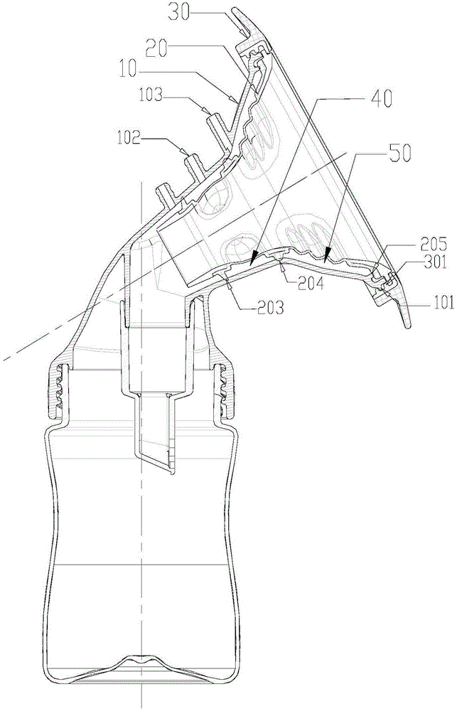
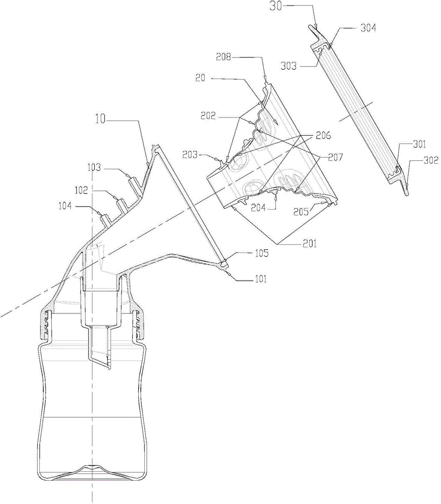
[0023] Such as figure 1 , 2 As shown, a cup of an automatic massage breast pump, the cup is roughly in the shape of a bell mouth, including an outer cup 10, an inner cup 20 and an outer ring 30, and the outer surface of the outer cup 10 is provided with an external thread 101; the outer cup 10 The other end is provided with the mounting thread that is connected with the feeding bottle, and the negative pressure air pipe 104 that is connected with the external negative pressure air pump is also provided on the outer cup 10...


PUM


Abstract

The invention discloses a breast pump cup with an automatic massage function. The breast pump cup comprises an outer cup body, an inner cup body and an outer ring; the breast pump cup is approximately shaped as a horn mouth; the outer ring is fixed on the horn mouth end of the outer cup body through threads and is used for connecting the inner cup body and the inner cup body in a sealing manner; the outer side wall of the inner cup body is provided with at least one sealing spacer bar along the circumferential direction, and each sealing spacer bar and the inner cup body are integrally formed; a chamber is defined by the inner side wall of the outer cup body, the outer side wall of the inner cup body and the sealing spacer bars; an air pipe which is communicated with the chamber is arranged on the outer cup body. After the structure is adopted, the sealing spacer bars of the inner cup body do not move relative to the inner wall of the outer cup body in an assembling process and thus do not generate a huge friction force, so that the outer ring can be easily tightened so as to sufficiently ensure that the sealing spacer bars of the inner cup body and the inner wall of the outer cup body are tightly matched, and thus the complete sealability of a massage airbag cavity is realized, and sufficient and stable force is provided for massage.

Description

technical field [0001] The invention relates to a breast pump. More specifically, it relates to an automatic massaging breast pump cup. Background technique [0002] Most of the breast pumps currently on the market generate negative pressure in the breast shield, thereby forcing the user's breasts to expand and produce milk. Since the negative pressure is used to act on the breasts, it is easy to form a pull on the nipples, which will cause the user's breasts to swell and produce milk. Painful, very uncomfortable. [0003] CN 203710436U discloses a breast shield and a breast pump with such a breast shield. The breast shield is an inner and outer double-layer structure that is closed to each other to form a deformable space. A positive pressure air path with an air pump is arranged in the deformable space. Positive pressure hole for type connection. The positive pressure generated by the air pump in the deformable space is used to squeeze or knead the mother's breast throu...

Claims


Application Information

Patent Timeline
Patent Type & Authority Applications(China)
IPC IPC(8): A61M1/06A61H9/00
CPCA61M1/064A61H9/0057A61M1/0697
Inventor 张立云
Owner 新文越婴童用品(上海)有限公司
Learn More