Power tool with signal generator
a technology of power tools and signal generators, applied in the direction of portable power-driven tools, manufacturing tools, drilling machines, etc., can solve the problems of damage to the ring gear or the fixed structure, the rotational ring gear is unable to engage the fixed structure in the housing smoothly, and the operation is not user-friendly
- Summary
- Abstract
- Description
- Claims
- Application Information
AI Technical Summary
Benefits of technology
Problems solved by technology
Method used
Image
Examples
first embodiment
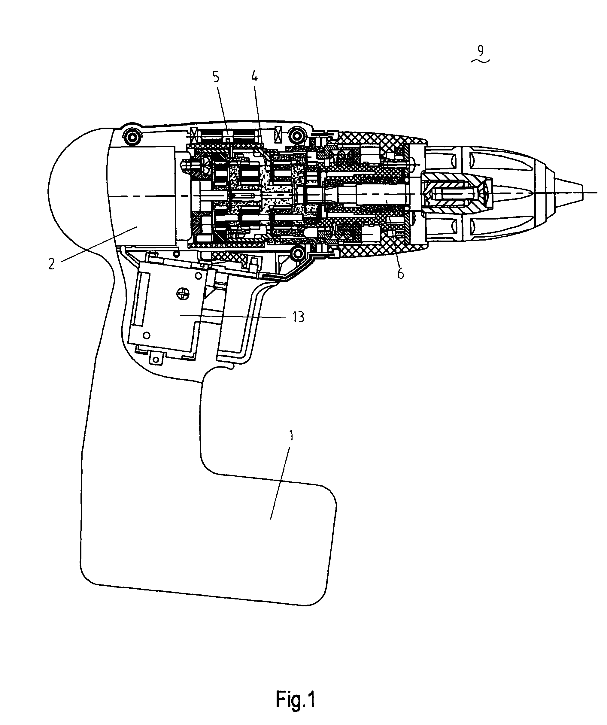
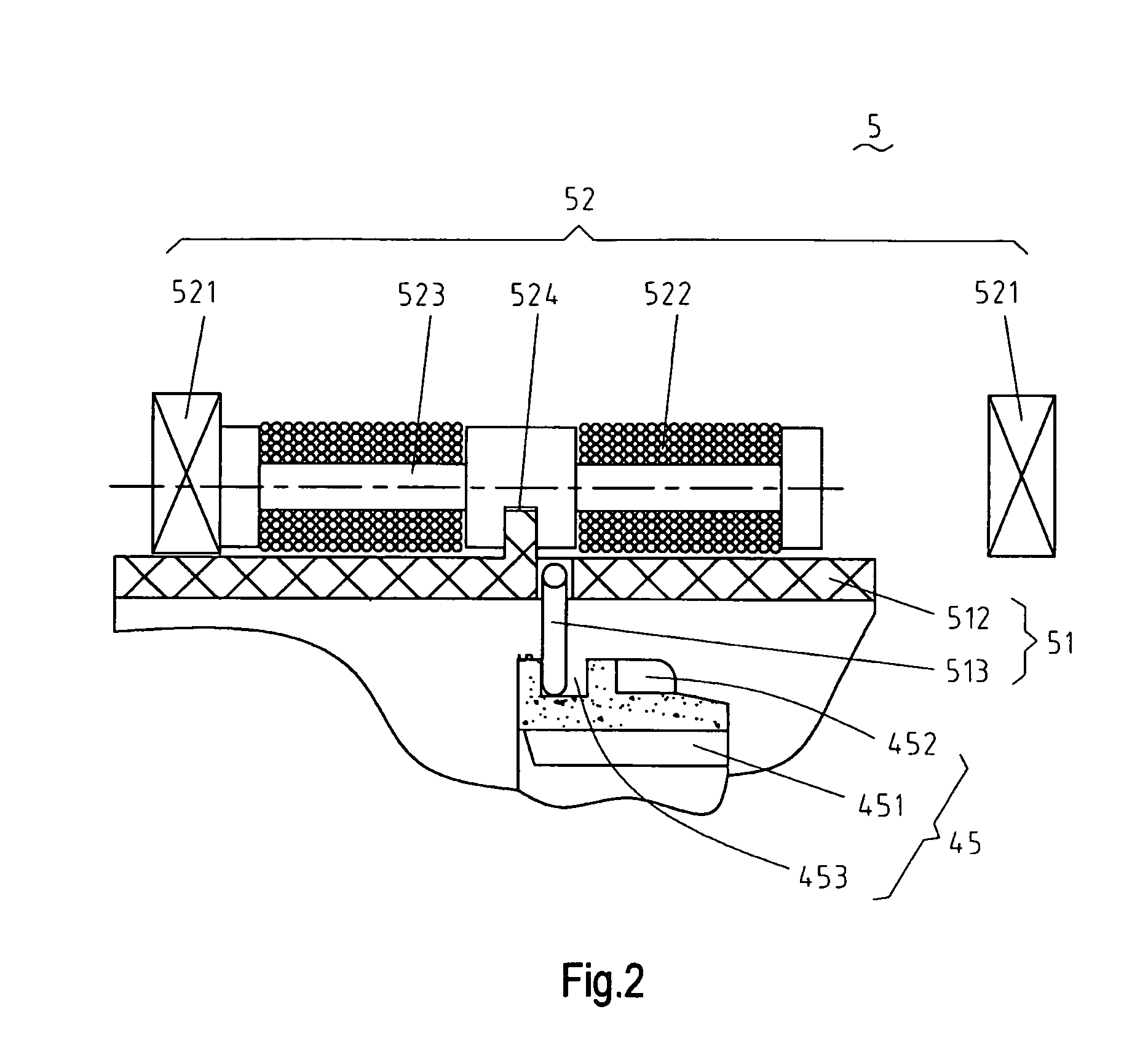
[0105]FIGS. 1 to 3b show a variable speed power tool in accordance with the present invention. The power tool 9 includes an electric motor 2, a power supply 1, a main switch 13 for starting or stopping the motor 2, an output shaft 6 and a gear transmission mechanism 4. The gear transmission mechanism 4 includes a first planetary gear train including a plurality of first planet gears 40 and a first planet carrier 41, a second planetary gear train including a plurality of second planet gears 42 and a second planet carrier 43, a rotationally fixed structure 44 fixed inside a housing 21 and an axially movable member 45. A driving mechanism 5 engages the gear transmission mechanism 4 and includes an actuating device 52 and a transmission member 51.
[0106]In the first embodiment, the actuating device 52 is electromagnetic and includes a pair of spaced apart permanent magnets 521, an iron core 523 located between the permanent magnets 521 and a coil 522 around the iron core 523. In the midd...
fourth embodiment
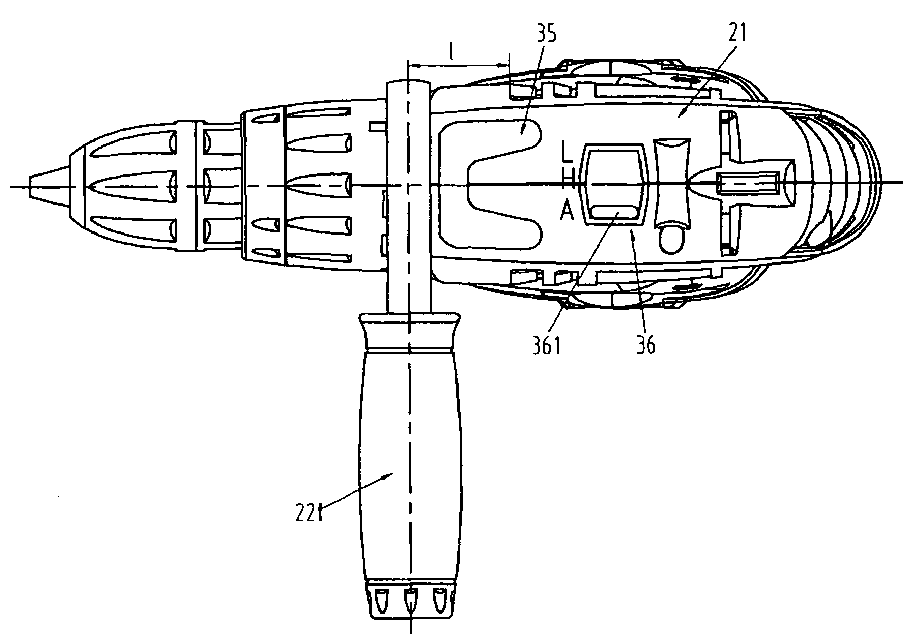
[0128]The signal generator 35 of the power tool of the present invention will be described with reference to FIGS. 15-17. As described above, when the signal generator 35 is activated, the electronic control system changes the direction of the electric current flowing through the driving mechanism 5 thereby activating the speed variation. Referring to FIG. 16, in conjunction with FIGS. 17a and 17b, the signal generator 35 includes a pair of switches disposed on respective halves of the housing 21. Each switch can activate the speed variation. By this arrangement, a left-handed operator and a right-handed operator can conveniently activate speed variation by a single touch of the switch.
[0129]FIGS. 17a and 17b show two forms of the switch. As shown in FIG. 17a, a pushbutton switch 351 is mounted on the housing 21 and a spring plate 353 is mounted on the housing spaced apart and covering the pushbutton switch 351. If the operator wishes to vary the output speed of the running power to...
sixth embodiment
[0134]The power tool of the sixth embodiment is not equipped with a speed mode selector button. Instead, two light emitting diodes (LED) 371, 372 are disposed on the housing 21 for indicating the high speed position and the low speed position respectively. In this embodiment, the power tool starts at a defaulted auto mode. On activating the signal generator 35, the auto mode is interrupted and the speed position will be switched. For example, the power tool initially runs in the auto mode at high speed and the H-LED 371 is illuminated to represent the high speed state. As the signal generator 35 is activated, the auto mode is interrupted and the speed state is switched to and maintained at low speed until the signal generator 35 is activated again or the power supplied to the motor 2 varies. If the signal generator 35 is activated again, the high speed state is resumed and maintained.
[0135]FIG. 20 is a simplified circuit diagram of the control system of a preferred embodiment of the...
PUM
| Property | Measurement | Unit |
|---|---|---|
| voltage | aaaaa | aaaaa |
| voltage | aaaaa | aaaaa |
| voltage | aaaaa | aaaaa |
Abstract
Description
Claims
Application Information
 - R&D
- Intellectual Property
- Life Sciences
- Materials
- Tech Scout
- Unparalleled Data Quality
- Higher Quality Content
- 60% Fewer Hallucinations
Browse by: Latest US Patents, China's latest patents, Technical Efficacy Thesaurus, Application Domain, Technology Topic, Popular Technical Reports.
© 2025 PatSnap. All rights reserved.Legal|Privacy policy|Modern Slavery Act Transparency Statement|Sitemap|About US| Contact US: help@patsnap.com


