
Gateway load balancing protocol

Active Publication Date: 2011-02-01
CISCO TECH INC
View PDF234 Cites 119 Cited by
  • Summary
  • Abstract
  • Description
  • Claims
  • Application Information

AI Technical Summary

Benefits of technology

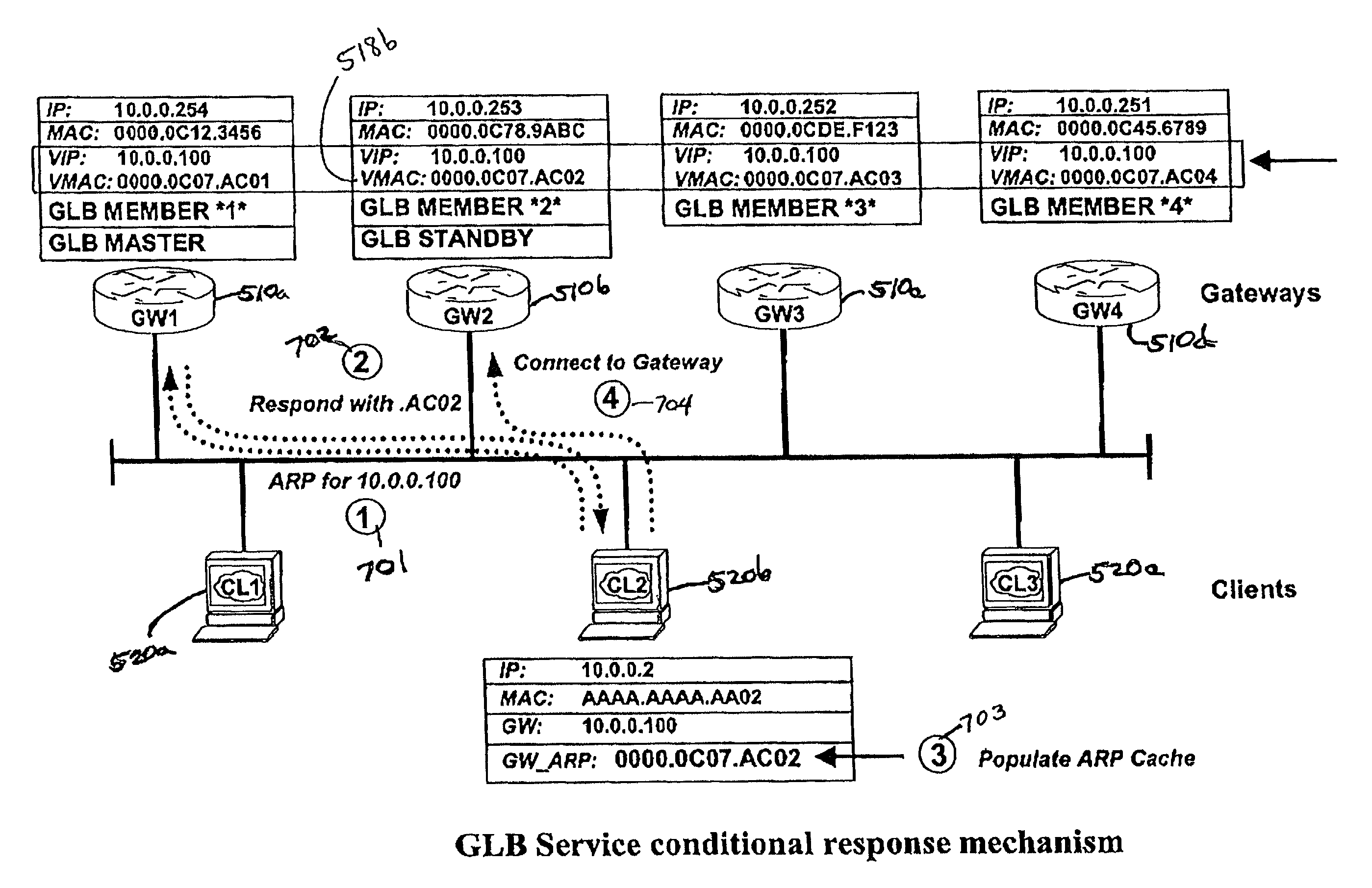
[0014]The present invention relates to gateway load balancing systems using more than one gateway device in a gateway device group for communications directed outside of a LAN. Generally, the invention includes load balancing and failover services. In the load balancing arrangement, hosts that send ARP messages to a shared virtual IP address receive replies from one of the gateway devices in the gateway device group, directing the host to address outgoing communications to a virtual MAC address assigned to one of the gateway devices. Hosts a

Problems solved by technology

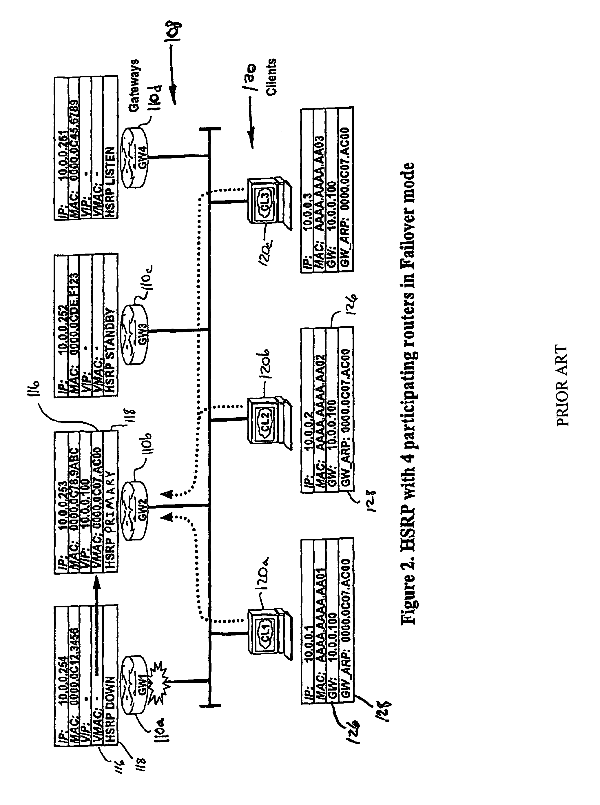
Unfortunately, a router may, for a variety of reasons, become inoperative (e.g., a power failure, rebooting, scheduled maintenance, etc.).
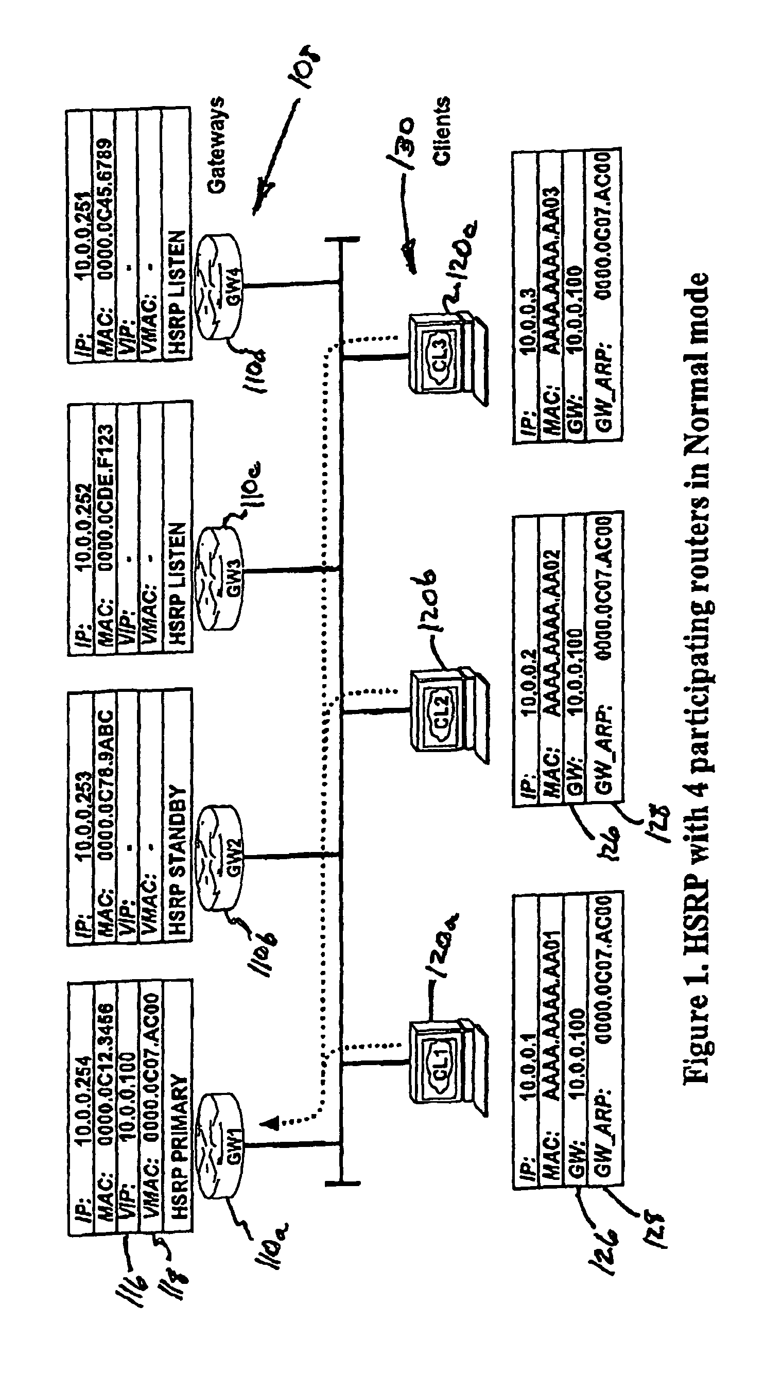
Such potential router failure has led to the development and use of redundant systems, systems having more than one router to provide a back up in the event of primary router failure.
However, because both RIP and IRDP require that the host be dynamically involved in the router selection, performance may be reduced and special host modifications and management may be required.
It does not keep track of available routers or make decisions to switch to different routers.
This requires very little effort on the host's part, but has a serious danger.
If the default router fails, the host can not send packets outside of its LAN.
Unfortunately, such systems have been used in mission critical applications such as stock trading.
The administrative task of dividing hosts among multiple default gateways can be tedious and requires customization of the system which many users would prefer to avoid.
Many users, however, are relinquishing the need for STP in such triangular formations, meaning that PVST-based load balancing will no longer be an option.
However, as seen from the foregoing examples, a one VLAN system can defeat current load balancing schemes.
Current methods requiring multiple VLANs at the access layer to achieve load balancing may not suffice or work within various users' systems.

Method used


Image

  • Gateway load balancing protocol
  • Gateway load balancing protocol
  • Gateway load balancing protocol

Examples


Embodiment Construction

1. Definitions

[0034]Reference will now be made in detail to the preferred embodiment of the invention. An example of the preferred embodiment utilizing products, protocols, methods, systems and other technology developed, sold and / or used by Cisco Systems is illustrated in the accompanying drawings. While the invention will be described in conjunction with that preferred embodiment, it will be understood that it is not intended to limit the invention to one preferred embodiment or to its implementation solely in connection with Cisco products and systems. On the contrary, the following description is intended to cover alternatives, modifications, and equivalents as may be included within the spirit and scope of the invention as defined by the appended claims. In the following description, numerous specific details are set forth in order to provide a thorough understanding of the present invention. The present invention may be practiced without some or all of these specific details. ...


PUM


Abstract

Gateway load balancing and failover methods, apparatus and systems use more than one gateway device in a gateway device group for communications directed outside of a LAN. In the load balancing arrangement, hosts that send ARP messages to a shared virtual IP address receive replies from one of the gateway devices in the gateway device group, directing the host to address outgoing communications to a virtual MAC address assigned to one of the gateway devices. Hosts are assigned virtual MAC addresses for the gateway devices according to a prescribed algorithm or methodology. In the event that one member of the gateway device group fails, the outgoing communications that would have been handled by the failed gateway device are re-assigned to another member of the gateway device group. A master gateway device controls address assignment and failover features. In the event that the master fails, additional steps are taken to appoint or elect a new master and ensure continuity in the load balancing function.

Description

BACKGROUND OF THE INVENTION[0001]The present invention relates generally to network systems having redundant default gateways and / or routers for receiving traffic from multiple hosts on a LAN. More particularly, the present invention relates to methods and apparatuses for deterministic load balancing across redundant gateway services for a common IP subnet.[0002]Local area networks (LANs) are commonly connected with one another through one or more routers so that a host (a PC or other arbitrary LAN entity) on one LAN can communicate with other hosts on different LANs. Typically, the host is able to communicate directly only with the entities on its local LAN segment. When it receives a request to send a data packet to an address that it does not recognize as being local, it communicates through a router (or other layer-3 device) which determines how to direct the packet between the host and the destination address. Unfortunately, a router may, for a variety of reasons, become inoper...

Claims


Application Information

Patent Timeline
IPC IPC(8): G01R31/08
CPCH04L29/12028H04L29/12207H04L29/12839H04L61/103H04L61/20H04L61/6022H04L67/1036H04L67/1002H04L61/50H04L2101/622H04L67/1001
Inventor NOSELLA, THOMAS J.WILSON, IAN HERBERT
Owner CISCO TECH INC
Learn More