
Incorporation of axial system response in iterative reconstruction from axially compressed data of cylindrical scanner using on-the-fly computing

a cylindrical scanner and axial system technology, applied in the field of medical imaging reconstruction, can solve the problems of a daunting computational challenge, limited reconstructed image accuracy, and relatively low computational cost, and achieve the effect of relatively low computational cos

Inactive Publication Date: 2011-01-25
SIEMENS MEDICAL SOLUTIONS USA INC
View PDF1 Cites 6 Cited by
  • Summary
  • Abstract
  • Description
  • Claims
  • Application Information

AI Technical Summary

Benefits of technology

The patent describes a method and system for creating tomographic images that incorporate information about the axial system response. This involves approximating the spreading of signals in image space as depth-independent, and combining the signals to produce large data sets. The system then uses a back projector to assemble the data for each angle. The technical effect of this invention is to improve the accuracy and resolution of medical imaging devices.

Problems solved by technology

Reconstruction of images from such projections is a problem to which much attention has been paid over the last 30 years, and many analytical and iterative reconstruction schemes exist.
While these algorithms can be realized with relatively low computational cost, the accuracy of the reconstructed images is limited by the approximation implicit in the line integral model on which the reconstruction formulas are based.
However, iterative 3D reconstruction represents a daunting computational challenge.
While this method saves on computational power, it is still a time consuming task.
Simple back projection convolves any f (x, y) with 1 / r, thus, the image gets severely blurred and distorted.
The major problem of this method is the unrealistic discontinuity of the model.
The major criticism of this algorithm is that the spatial resolution of the reprojection is lessened by the finite spacing between rays.
Furthermore, increasing the number of pixels does not contribute to a reduction in this spacing, but does greatly increase processing time.

Method used


Image

  • Incorporation of axial system response in iterative reconstruction from axially compressed data of cylindrical scanner using on-the-fly computing
  • Incorporation of axial system response in iterative reconstruction from axially compressed data of cylindrical scanner using on-the-fly computing
  • Incorporation of axial system response in iterative reconstruction from axially compressed data of cylindrical scanner using on-the-fly computing

Examples


Embodiment Construction

[0029]As required, disclosures herein provide detailed embodiments of the present invention; however, the disclosed embodiments are merely exemplary of the invention that may be embodied in various and alternative forms. Therefore, there is no intent that specific structural and functional details should be limiting, but rather the intention is that they provide a basis for the claims and as a representative basis for teaching one skilled in the art to variously employ the present invention.

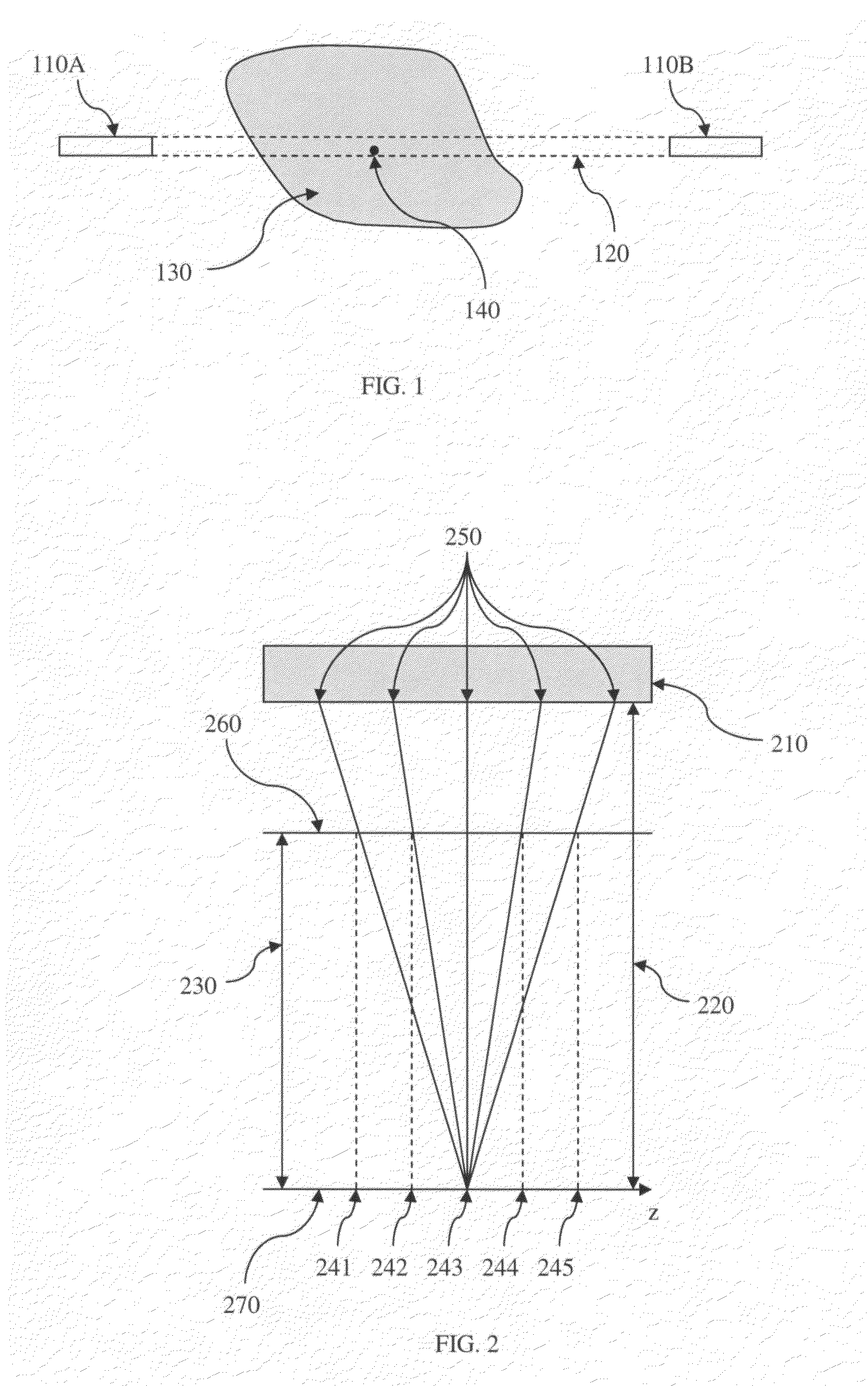
[0030]FIG. 1 is a representation of a LOR. An annihilation event 140 in imaged object mass 130 may emit two simultaneous gamma rays (not shown) traveling substantially 180° apart. The gamma rays may travel out of scanned mass 130 and may be detected by block detectors 110A and 110B, where the detection area of the block detector defines the minimum area or maximum resolution within which the position of an incident gamma ray may be determined. Since block detectors 110A and 110B are unable to det...


PUM


Abstract

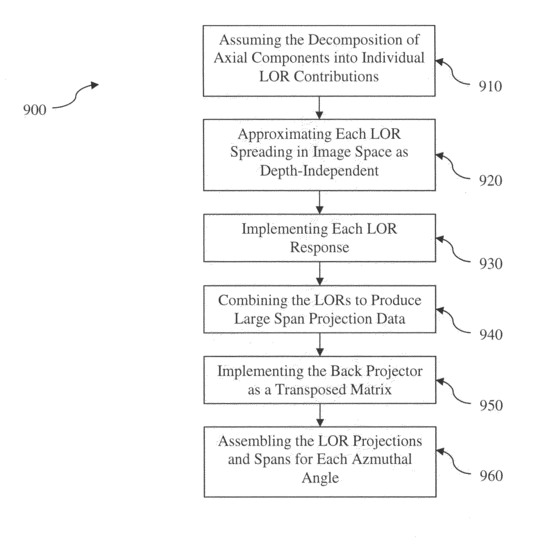
A method and system for reconstructing PET image data from a cylindrical PET scanner by incorporation of axial system response. The method includes the steps of: assuming the decomposition of axial components into individual line-of-response (LOR) contributions, approximating each LOR spreading in image space as depth-independent, implementing each LOR response, combining the LORs to produce large span projection data, implementing the back projector as a transposed matrix, and assembling the LOR projections and spans for each azimuthal angle.

Description

TECHNICAL FIELD[0001]The current invention is in the field of medical imaging reconstruction.BACKGROUND OF THE INVENTION[0002]Medical imaging is one of the most useful diagnostic tools available in modern medicine. Medical imaging allows medical personnel to non-intrusively look into a living body in order to detect and assess many types of injuries, diseases, conditions, etc. Medical imaging allows doctors and technicians to more easily and correctly make a diagnosis, decide on a treatment, prescribe medication, perform surgery or other treatments, etc.[0003]There are medical imaging processes of many types and for many different purposes, situations, or uses. They commonly share the ability to create an image of a bodily region of a patient, and can do so non-invasively. Examples of some common medical imaging types are nuclear medical (NM) imaging such as positron emission tomography (PET) and single photon emission computed tomography (SPECT), electron-beam X-ray computed tomogr...

Claims


Application Information

Patent Timeline
Patent Type & Authority Patents(United States)
IPC IPC(8): G06K9/00
CPCG01T1/1644
Inventor PANIN, VLADIMIRKEHREN, FRANKCASEY, MICHAEL E.
Owner SIEMENS MEDICAL SOLUTIONS USA INC
Learn More