
Methods and apparatus for real-time error correction

a technology of positron emission tomography and real-time error correction, which is applied in the direction of instruments, radiation measurement, measurement devices, etc., can solve the problems of inability to correct changes in loss rates during a single frame, multiple sources of annihilation detection errors, and loss of annihilation data for image reconstruction purposes

Active Publication Date: 2006-11-07
GENERAL ELECTRIC CO
View PDF19 Cites 6 Cited by
  • Summary
  • Abstract
  • Description
  • Claims
  • Application Information

AI Technical Summary

Benefits of technology

This approach enables precise correction of deadtime losses and random coincidences, resulting in more accurate image reconstruction, especially during dynamic imaging processes like cardiac scans, by accounting for changes in activity and external sources, thereby enhancing diagnostic imaging reliability and accuracy.

Problems solved by technology

However, during an acquisition period there are several sources of annihilation detection error.
In these cases, at least one of the annihilations is not recognized and that annihilation data is lost for the purposes of image reconstruction.
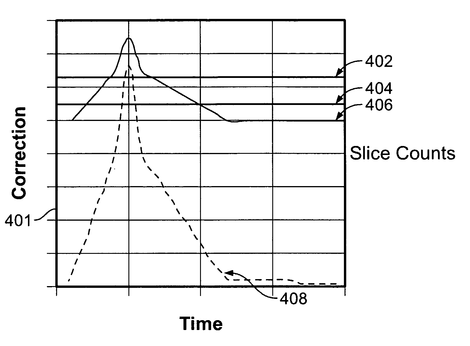
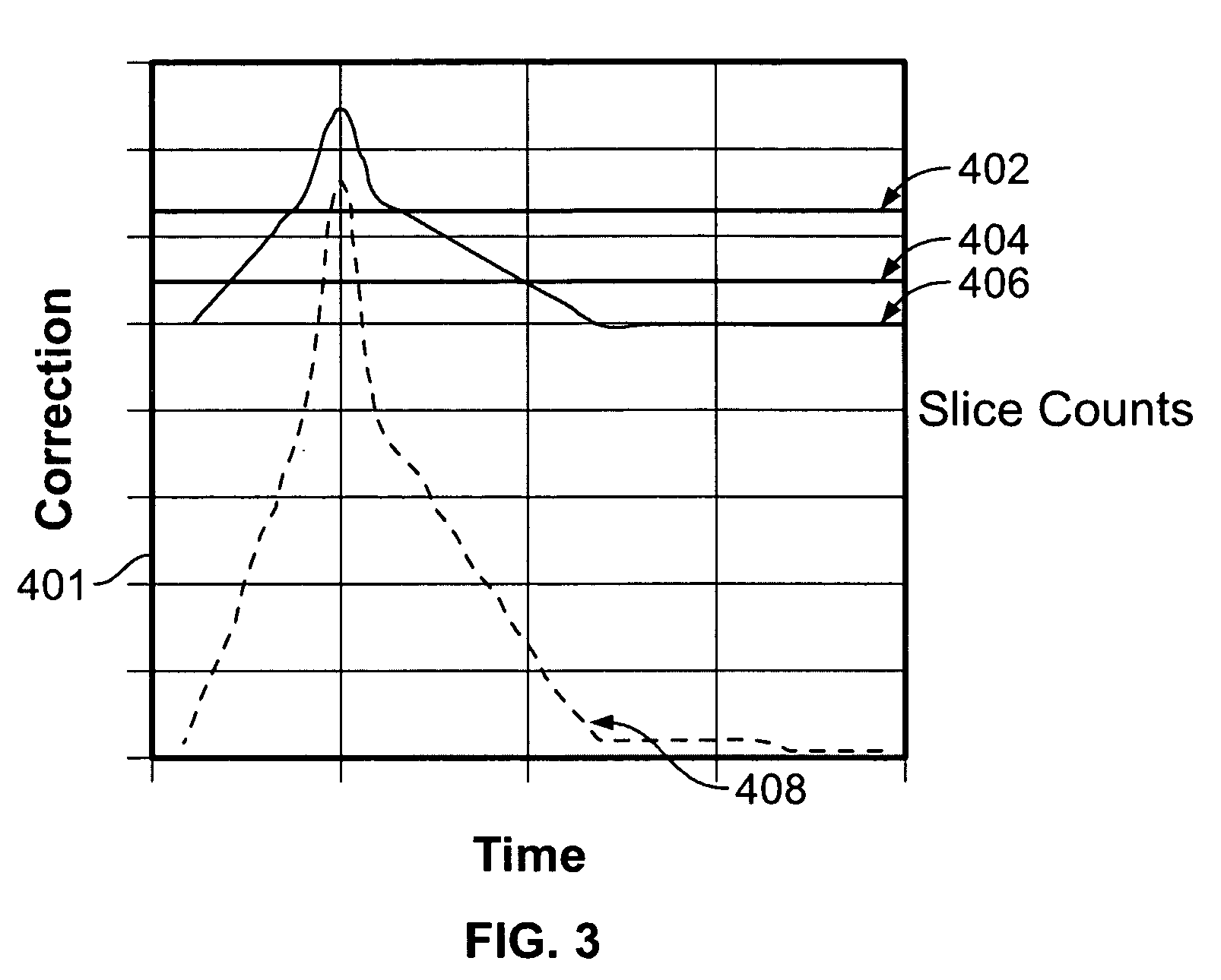
However, because the measured value is collected once per data frame, changes in loss rates during a single frame cannot be corrected for.

Method used


Image

  • Methods and apparatus for real-time error correction
  • Methods and apparatus for real-time error correction
  • Methods and apparatus for real-time error correction

Examples


Embodiment Construction

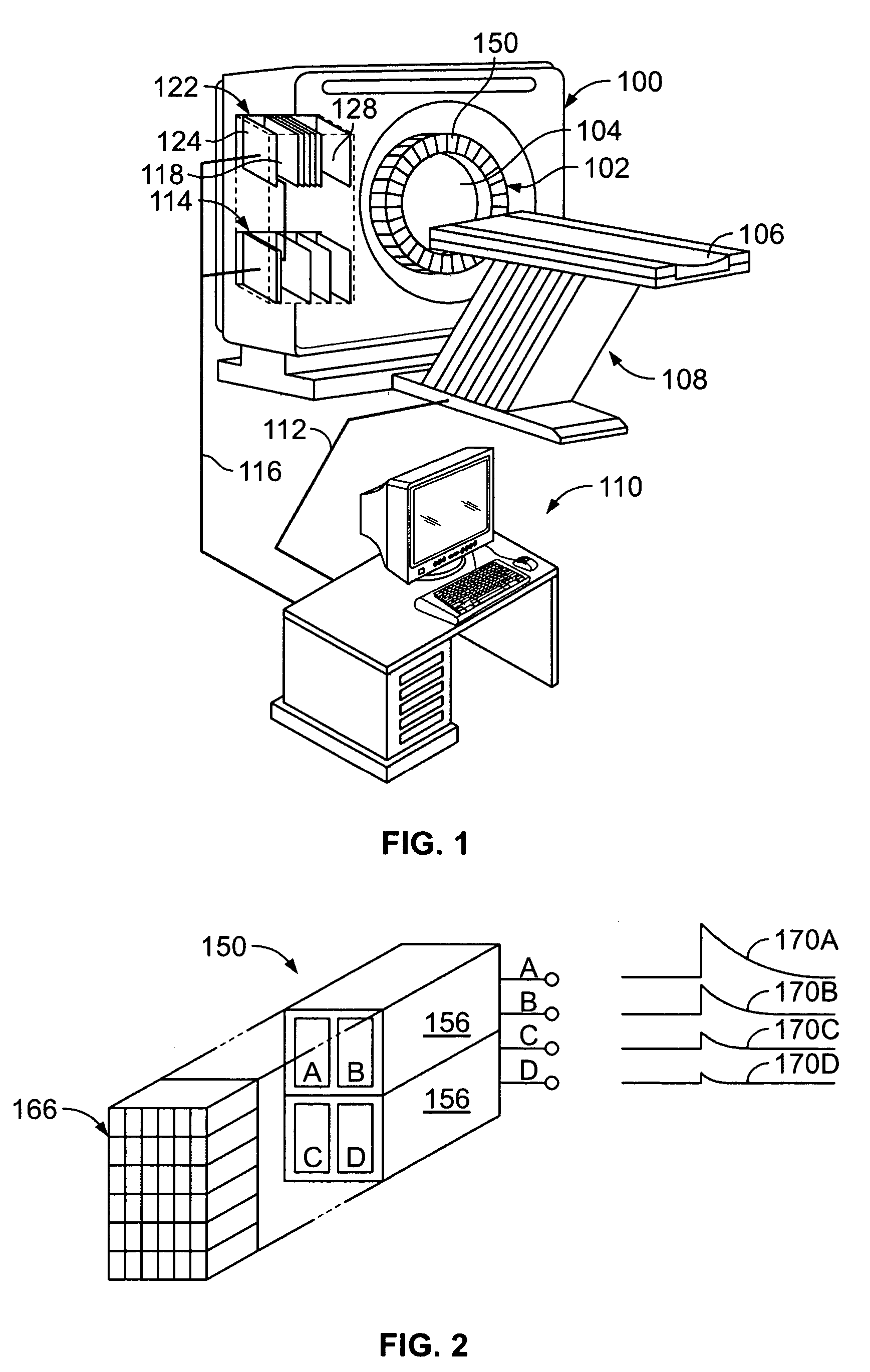
[0014]FIG. 1 is a perspective view of an exemplary PET scanner system that includes a gantry 100 which supports a detector ring assembly 102 about a central axis, or bore 104. A patient table 108 is positioned adjacent gantry 100 and is aligned with the central axis of the bore 104. A patient table controller (not shown) moves the table bed 106 into the bore 104 in response to commands received from an operator work station 110 through a serial communications link 112. A gantry controller 114 is mounted within the gantry 100 and is responsive to commands received from the operator work station 110 through a second serial communication link 116 to operate the gantry 100. For example, the gantry 100 can perform a “transmission scan” with a calibrated radionuclide source to acquire attenuation measurements, or it can perform a normal scan, in which positron annihilation events are counted and an image is reconstructed.

[0015]Detector ring 102 may include a plurality of detector modules ...


PUM


Abstract

Methods and apparatus for correcting for at least one of deadtime losses and random coincidences in a positron emission tomography (PET) medical imaging device having a plurality of detectors at successive locations circumferentially spaced about a viewing area, the method comprising, receiving signals indicative of positron-electron annihilation events occurring along a line of response between pairs of detectors for a plurality of predetermined time segments of data acquisition of the events, calculating a correction sinogram for each predetermined time segment from data acquired during each respective single time segment, calculating corrected counts in the correction sinogram for each time segment, calculating a time-weighted correction sinogram for each time segment, combining the time-weighted correction sinogram to generate an acquisition sinogram, and generating an image from the acquisition sinogram.

Description

BACKGROUND OF THE INVENTION[0001]This invention relates generally to positron emission tomography (PET) scanners, and more particularly to methods and apparatus for correcting errors during data image reconstruction.[0002]Positrons are positively charged electrons which are emitted by radionuclides that have been prepared using a cyclotron or other device. The radionuclides are employed as radioactive tracers called “radiopharmaceuticals” by incorporating them into substances that are injected into the patient and become involved in such processes as glucose metabolism, fatty acid metabolism and protein synthesis.[0003]As the radionuclides decay, they emit positrons. The positrons travel a very short distance before they encounter an electron, and when this occurs, they are annihilated and converted into two photons, or gamma rays. This annihilation event is characterized by two features which are pertinent to PET scanners: each gamma ray has an energy of 511 keV and the two gamma r...

Claims


Application Information

Patent Timeline
Patent Type & Authority Patents(United States)
IPC IPC(8): G01T1/164
CPCG01T1/172G01T1/2985A61B6/037G01T1/171G01T1/1611
Inventor WILLIAMS, JOHN JAYMCDANIEL, DAVID LEO
Owner GENERAL ELECTRIC CO
Learn More