
Immersion exposure apparatus and immersion exposure method, and device manufacturing method

a technology of immersion exposure and exposure apparatus, which is applied in the direction of photomechanical treatment, printing, instruments, etc., can solve the problems of deteriorating exposure accuracy, undesirable conditions, and reducing the output of the exposure apparatus, so as to achieve efficient exposure and high productivity. , the effect of efficient exposur

Inactive Publication Date: 2011-01-18
NIKON CORP
View PDF95 Cites 7 Cited by
  • Summary
  • Abstract
  • Description
  • Claims
  • Application Information

AI Technical Summary

Benefits of technology

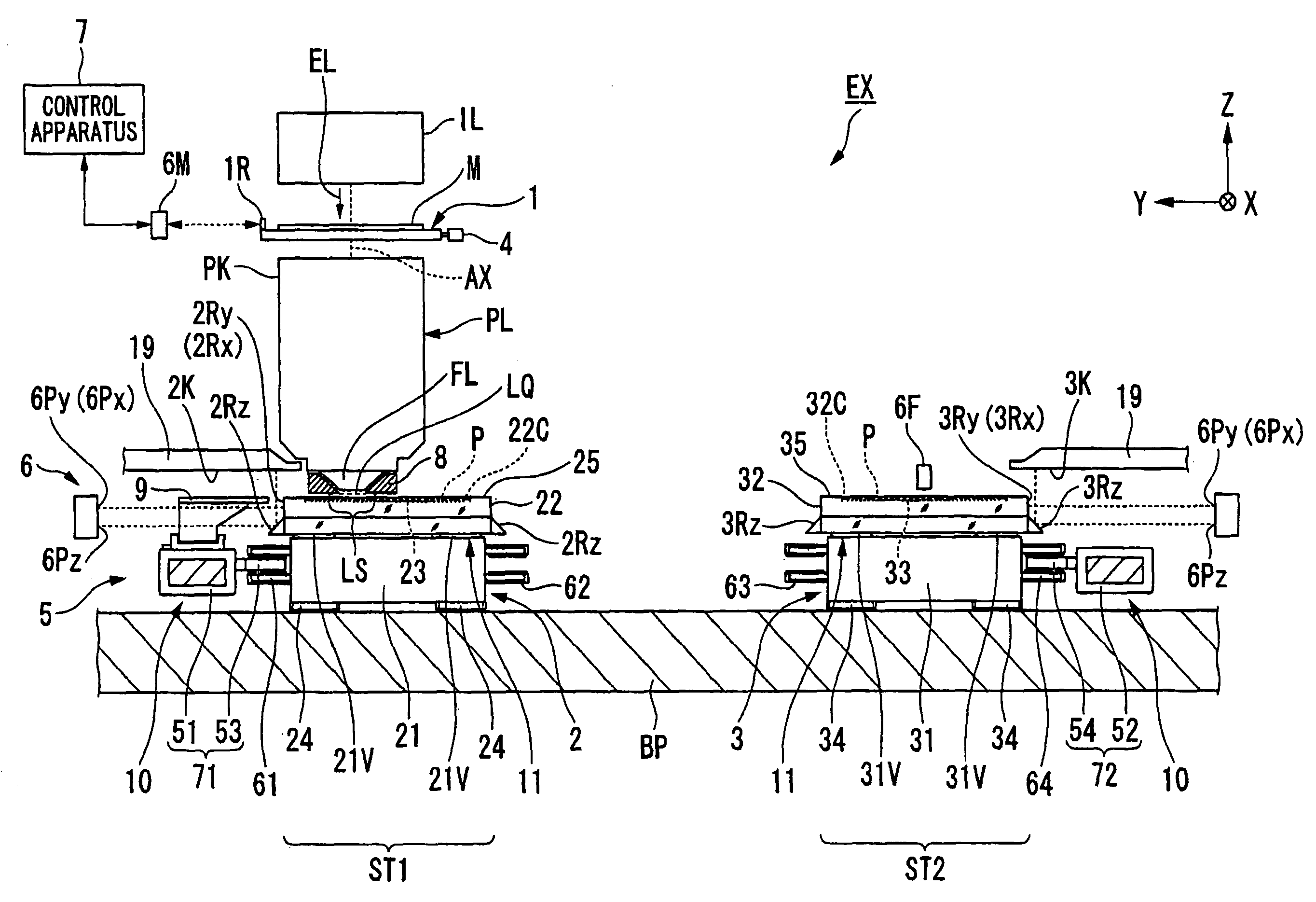
The present invention provides an immersion type exposure apparatus and method for efficiently exposing a substrate with an exposure beam. The apparatus includes an optical member, a first movable member, a second movable member, a first connection member, a second connection member, a third movable member, a liquid holding member, and a first driving device. The method involves moving the first movable member to position the substrate facing the optical member, moving the second movable member to position the substrate in a different region, and moving the third movable member to change the relative position between the movable members. The substrate can be efficiently exposed and a device with desired performance can be manufactured with high productivity.

Problems solved by technology

In an immersion exposure apparatus, for example, if all of the liquid is recovered each time a substrate stage is separated from the projection optical system, such as at the time of exchanging a substrate, there is a possibility that throughput of the exposure apparatus declines.
Moreover, when all of the liquid is recovered and the light emitting surface of the projection optical system is changed from a wet state into a dry state, there is a possibility that vaporization of the liquid causes formation of adhesion marks (water marks) of the liquid on the light emitting surface of the projection optical system, and produces temperature change, thus deteriorating the exposure accuracy.
In a multi-stage type exposure apparatus, as in the conventional way, in the case where there is an attempt to keep the light emitting surface of the projection optical system wet with a liquid at all times by holding a cap member (shutter member) so as to face the light emitting surface of the projection optical system, there is a possibility that an undesirable conditions exists where the cap member drops down, the liquid on the cap member leaks, or the like.
Moreover, there is a possibility that the throughput of the exposure apparatus declines due to the operation for transferring the cap member to / from the substrate stage.

Method used


Image

  • Immersion exposure apparatus and immersion exposure method, and device manufacturing method
  • Immersion exposure apparatus and immersion exposure method, and device manufacturing method
  • Immersion exposure apparatus and immersion exposure method, and device manufacturing method

Examples


Embodiment Construction

[0031]Hereunder is a description of embodiments of the present invention with reference to the drawings. However the present invention is not limited to this description. In the following description, an XYZ rectangular co-ordinate system is established, and the positional relationship of respective members is described with reference to this XYZ rectangular co-ordinate system. A predetermined direction within a horizontal plane is made the X axis direction, a direction orthogonal to the X axis direction in the horizontal plane is made the Y axis direction, and a direction orthogonal to both the X axis direction and the Y axis direction (that is, a perpendicular direction) is made the Z axis direction. Furthermore, rotation (inclination) directions about the X axis, the Y axis and the Z axis, are made the θX, the θY, and the θZ directions respectively.

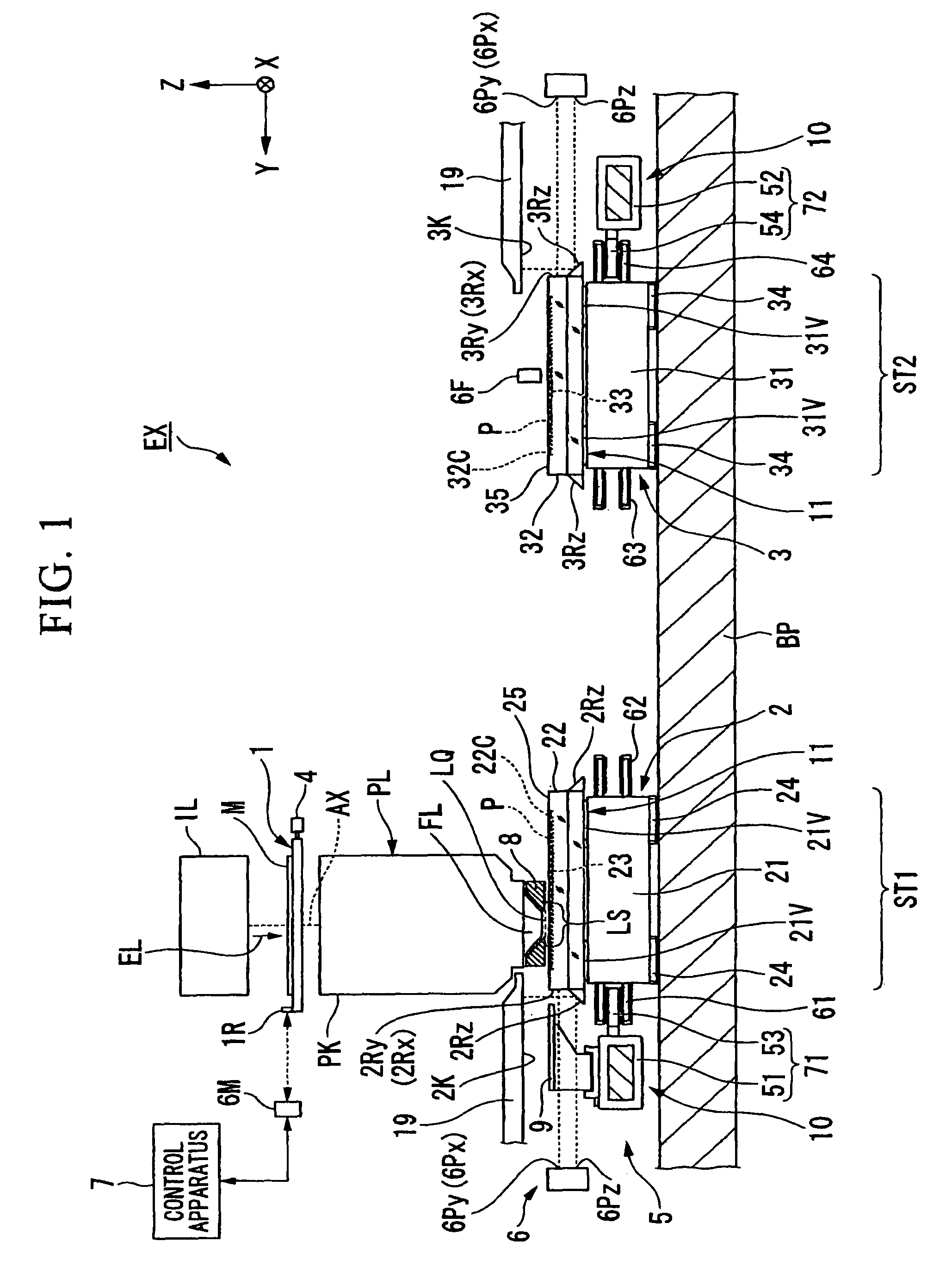
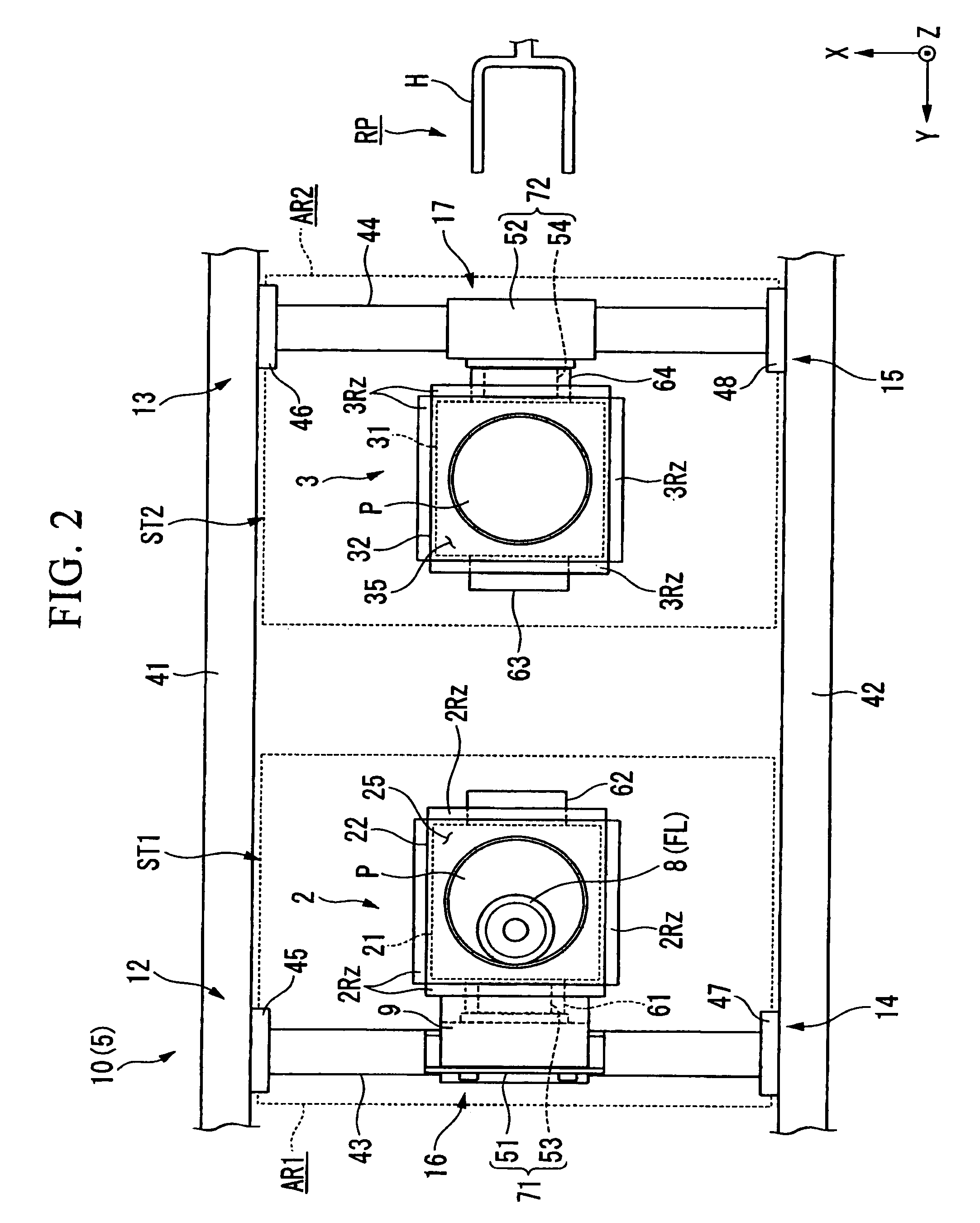
[0032]FIG. 1 is a schematic block diagram that shows the exposure apparatus EX according to the present embodiment. In FIG. 1, the ex...


PUM


Abstract

An immersion type exposure apparatus comprises: an optical member from which an exposure beam is emitted; a first movable member that is movable while holding a substrate, in a predetermined region including a first region including a position facing the optical member and a second region different from the first region; a second movable member that is movable while holding the substrate independently from a first movable member, in a predetermined region including the first region and the second region; a first connection member that is releasably and alternately connected with the first movable member and the second movable member, and moves one movable member in the first region; a second connection member that is releasably and alternately connected with the first movable member and the second movable member, and moves the other movable member in the second region; and a third movable member that is provided on the first connection member and is movable to a position facing the optical member, and at least one of the first movable member, the second movable member, and the third movable member is moved to the position facing the optical member so that a beam path on the emitting side of the optical member is kept filled with a liquid.

Description

CROSS-REFERENCE TO RELATED APPLICATION[0001]This application is non-provisional application claiming benefit of provisional application No. 60 / 844,658, filed Sep. 15, 2006, the contents of which are incorporated herein by reference.BACKGROUND[0002]1. Field of the Invention[0003]The present invention relates to an immersion exposure apparatus and immersion exposure method, and a device manufacturing method.[0004]2. Description of Related Art[0005]In exposure apparatuses used in the photolithography process, immersion exposure apparatuses as disclosed in Japanese Unexamined Patent Application, First Publication No. 2004-289126 (corresponding to U.S. Pat. No. 6,952,253) and Japanese Unexamined Patent Application, First Publication No. 2004-289128 (corresponding to U.S. Pat. No. 7,075,616) which expose a substrate via a liquid are known. In addition, multi stage type (twin stage type) exposure apparatuses as disclosed in Published Japanese Translation No. 2000-511704 of PCT Internationa...

Claims


Application Information

Patent Timeline
Patent Type & Authority Patents(United States)
IPC IPC(8): G03B27/42G03B27/52G03B27/58
CPCG03F7/70733G03F7/70341H01L21/0274G03F7/2041G03F7/7055
Inventor KIUCHI, TOHRU
Owner NIKON CORP
Learn More