
Device and method to measure corneal biomechanical properties and its application to intraocular pressure measurement

Inactive Publication Date: 2011-01-18
JIM SON CHOU ACHEVE TECH
View PDF10 Cites 32 Cited by
  • Summary
  • Abstract
  • Description
  • Claims
  • Application Information

AI Technical Summary

Benefits of technology

[0021]Accordingly, our invention of a non-contact ophthalmic device provides a new method for measuring the biomechanical properties of the cornea and the intraocular pressure by recording the sequence of multiple dimensional corneal profiles after the impact of a discharge of fluid. The biomechanical properties of the cornea derived from the corneal profiles will thus eliminate the cornea factor from the intraocular pressure measurement. Several objects and advantages of the present invention are:
[0022]In accordance with the present invention, an ophthalmic device comprises a fluid discharge system, a real time image recording/analysis system that records and analyzes the topographic changes of the cornea due to the impact of fluid discharge and an algorithm to convert topographic changes to the bio-mechanical properties of the cornea.
[0023]In one innovative aspect, the present innovation relates to dynamic corneal topographer and methods and sequences used within such systems.

Problems solved by technology

However the promises to enhance the predictability of surgical outcomes were not met, debilitating visual complaints are reported.
The possibility of ectasia, the bulging of the cornea, after the ablation type of laser surgeries, for example LASIK, also demonstrates the unsatisfactory outcome of laser refractive surgeries due to the lack of biomechanical properties of corneas.
Although the incident rate of ectasia appears low now, LASIK has only been used in clinical practice in recent years and the long-term results are unknown.
Thus screening of the cornea for its biomechanical defects together with the cornea thickness radius of curvature and other physical parameters before LASIK type procedures is becoming more urgent.
This method requires contact of the patient's cornea with a pointed indenter and is not practical in the clinical setting.
This device is not able to provide other physical parameters of the cornea.
Because it is based on the reflection of limited points of light, the method suffers from the same reliability problem when the surface of the cornea is irregular as the non-contact tonometer suffers.
Furthermore, Luce's inventions, including U.S. Pat. No. 6,875,175, can not provide the physical parameters of the cornea, for example: radius of curvature and the thickness of the cornea, etc.
Another important clinical issue related to the lack of in vivo data of the cornea biomechanical properties has been demonstrated in the clinical monitoring of the intraocular pressure, an important indicator to control the progress of glaucoma.
This non-contact device has several disadvantages: the reading is inaccurate on irregular cornea surfaces due to its single point probing system; it overestimates the tension with increased tear film and ocular misalignment and the reading is variable due to the ocular pulses in the eye.
The device is of little clinical value above 30 mmHg due to lack of accuracy.
In spite of the difficult clinical technique, possible damage to the cornea, chances of communicating disease and questionable accuracy, the contact tonometer, particularly the Goldmann tonometer, is the still gold standard of the measurement because of the problems with non-contact tonometers.
This kind of variation was due to the fact that the thickness of the cornea alone does not account for the total resistance and effect of the cornea and thus the inaccuracy of the intraocular pressure.

Method used


Image

  • Device and method to measure corneal biomechanical properties and its application to intraocular pressure measurement
  • Device and method to measure corneal biomechanical properties and its application to intraocular pressure measurement
  • Device and method to measure corneal biomechanical properties and its application to intraocular pressure measurement

Examples


Embodiment Construction

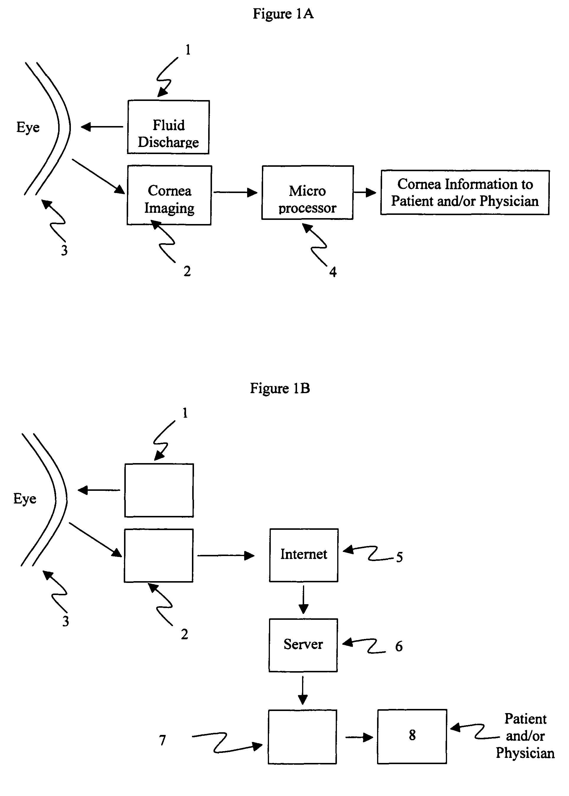
[0033]The system for use in the invention, as indicated in FIG. 1, has a fluid discharge device, 1, that discharges a pulse of the fluid with known stress profile and an image recording subsystem, 2, that records the profile of the cornea, 3, before, during and / or after the discharge of the fluid.

[0034]The cornea profiles obtained will then be used to derive the cornea parameters, e.g. the thickness, the radius of curvature, and biomechanical properties of cornea like stress-strain relationship etc., and calculate the intraocular pressure according the analytical formula and / or numerical simulations, e.g. finite element method, as describe in FIG. 1.

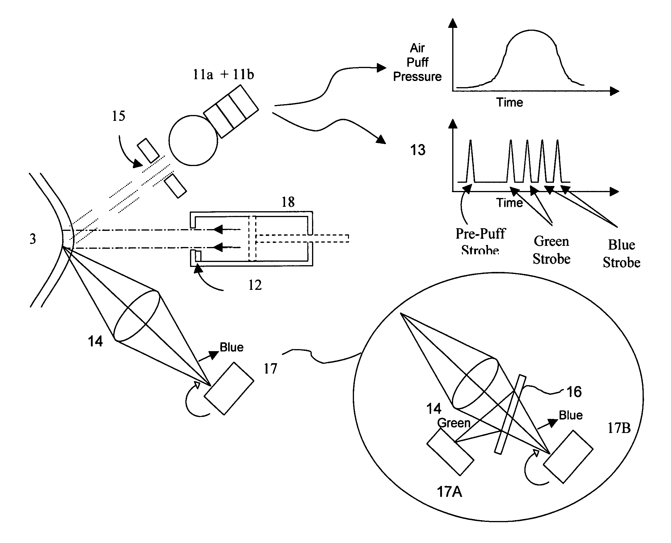
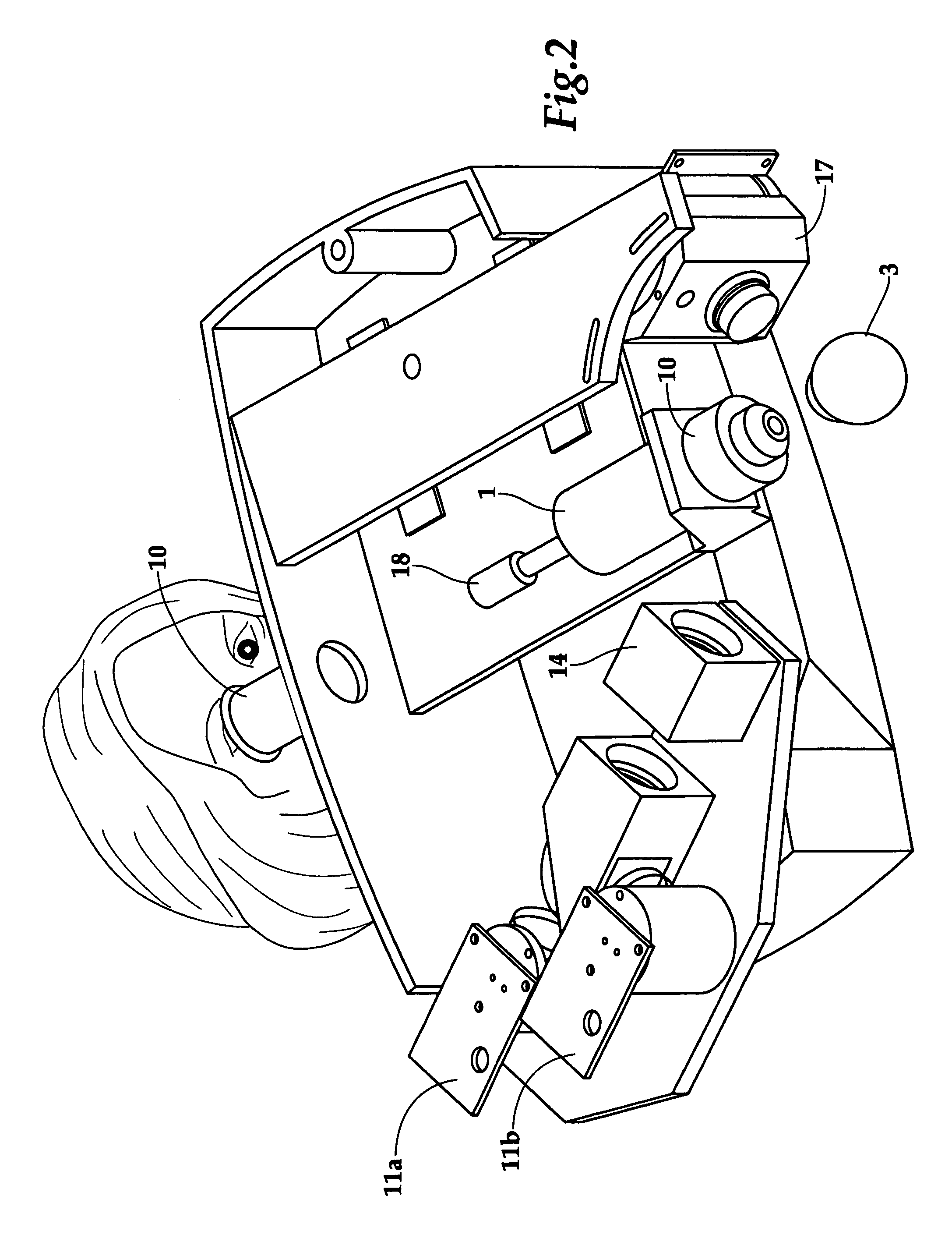
[0035]The fluid discharge device, 1, can be a generator that discharges air pulses. Our preferred embodiment is an enclosure with an orifice and a plunger, 18, of FIG. 2, driven by a solenoid or a linear motor, not shown in the drawing's. The plunger will drive the air through the orifice to create the impacting stress. The stress profil...


PUM


Abstract

This invention is a system, an apparatus and a method for measuring biomechanical properties of cornea and the intraocular pressure in vivo. More than one dimensional topographic information of the cornea is recorded and analyzed before and during the fluid discharge and converted to the stress-strain relationship and other cornea parameters, for example the cornea thickness and radius of curvature, etc. The deformation of cornea is initiated by a non-contact fluid discharge whose profile is predetermined and monitored in real time. Utilizing this non-contact topographer, the true intraocular pressure can be derived from the response of the cornea due to the impact of fluid discharge and the corneal topographic parameters. One embodiment of this invention includes the use of a multiple color strobe light / multiple detector system to record the corneal topographic deformation due to the impact of fluid discharge.

Description

CROSS-REFERENCE TO RELATED APPLICATIONS[0001]This application claims the benefit of provisional patent applications with Ser. No. 60 / 639,059 filed 2004 Dec. 22, No. 60 / 662,260 filed 2005 Mar. 16 and 60 / 665,271 filed 2005 Mar. 25 by the present inventor.FEDERALLY SPONSORED RESEARCH[0002]Not ApplicableSEQUENCE LISTING OR PROGRAM[0003]Not ApplicableBACKGROUND OF THE INVENTION[0004]1. Field of the Invention[0005]This invention relates generally to a device and method that measures the biomechanical properties, the stress-strain relationship of the cornea together with the physical properties of a mammal's anterior chamber of the eye in vivo. The present innovation also applies to methods to monitor the intraocular pressure of a mammal eye.[0006]2. Prior Arts[0007]Cornea contributes more than 60% of refractive power of the vision system thus most of the refractive surgeries for vision corrections were performed on the cornea. Current diagnostic instruments used in the eye clinics are abl...

Claims


Application Information

Patent Timeline
IPC IPC(8): A61B3/16
CPCA61B3/165
Inventor CHOU, JIM-SONHEINOLD, STEVEN SCOTTISMAEL, GEORGE BRYANTMOORE, RICHARD ARNOLD
Owner JIM SON CHOU ACHEVE TECH
Learn More