
Phase error detecting device, waveform shaping device and optical disc device

a phase error and waveform technology, applied in the direction of digital signal error detection/correction, amplitude demodulation, transmission monitoring, etc., can solve the problems of prml, deterioration of snr (signal noise rate), and increase of intersymbol interference, so as to enhance the accuracy of detecting phase errors.

Active Publication Date: 2011-01-11
PANASONIC CORP
View PDF7 Cites 8 Cited by
  • Summary
  • Abstract
  • Description
  • Claims
  • Application Information

AI Technical Summary

Benefits of technology

[0010]The invention was devised to solve the problems discussed above and has an object to provide a phase error detecting device, a waveform shaping device, and an optical disc device each capable of generating a reproduction clock signal in a stable manner.
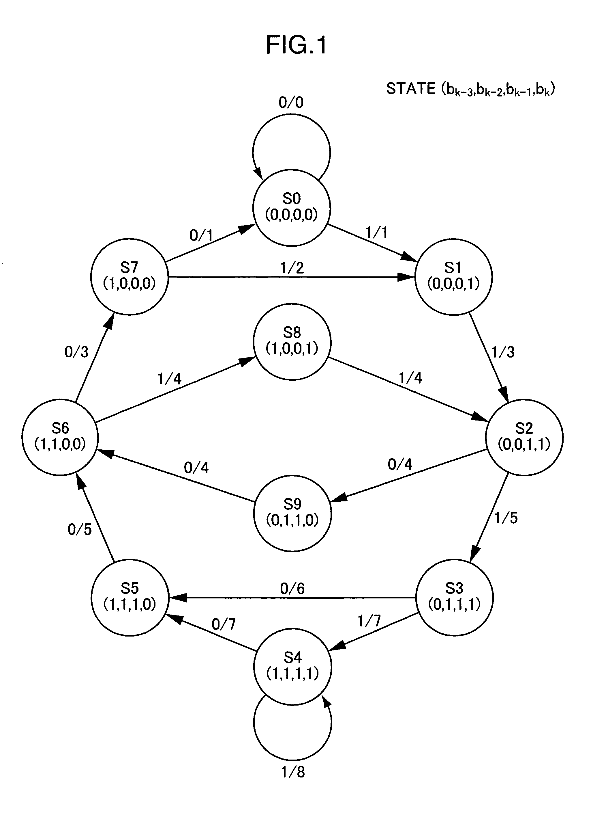
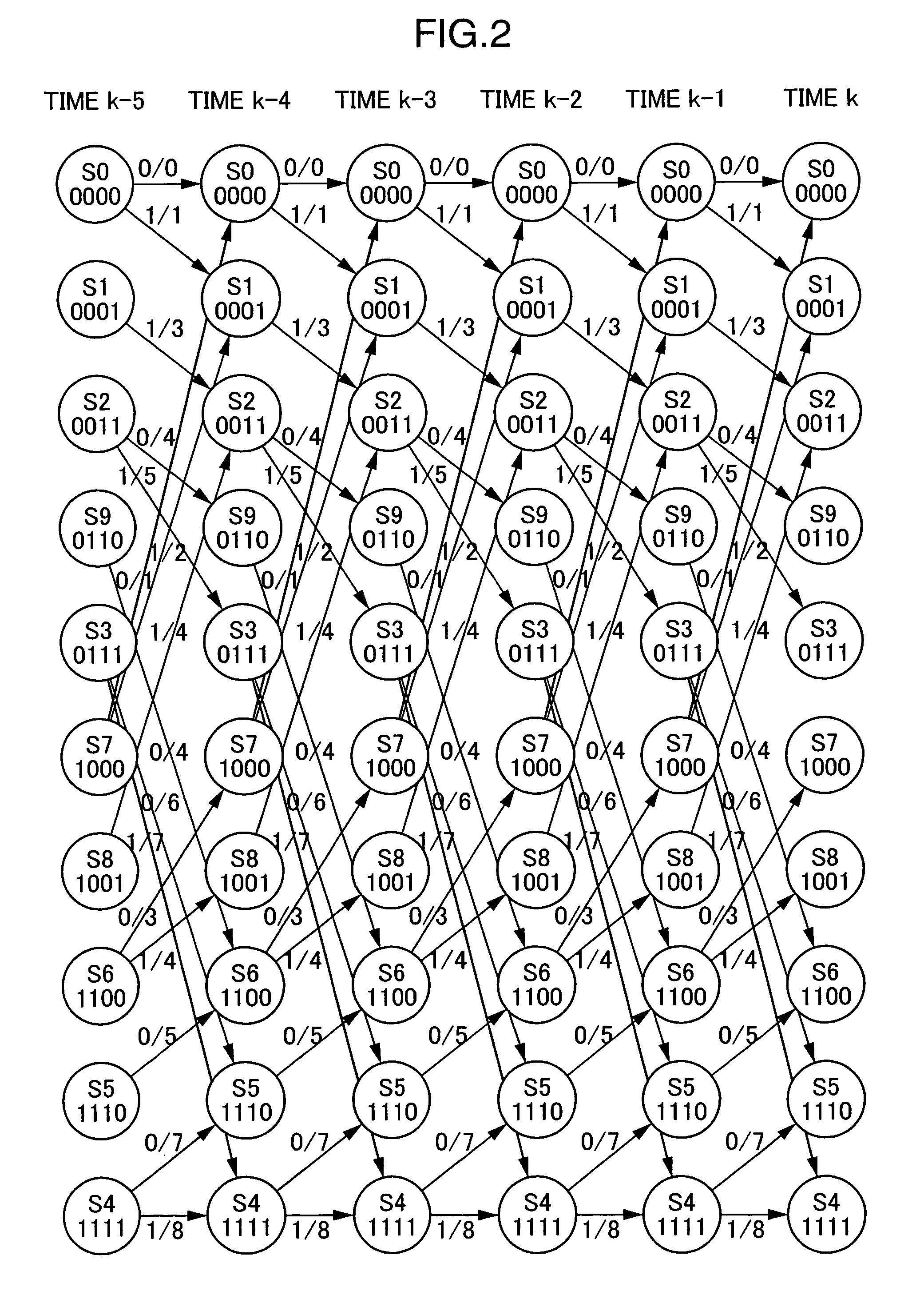
[0013]Accordingly, the phase error is extracted during the maximum likelihood decoding using the state transition patterns having only a single zero cross point among the differential metrics at a plurality of merging points at which a set of paths branched from a given state merges. Accuracy in detecting the phase error can be therefore enhanced, which makes it possible to generate a reproduction clock signal in a stable manner.

Problems solved by technology

An increase in intersymbol interference and deterioration of SNR (Signal Noise Rate) are therefore becoming more noticeable.
Meanwhile, a shift of the signal processing method from the level determination method to PRML poses a problem as to an evaluation method of a reproduced signal.
In addition, as an optical disc becomes further denser, intersymbol interference and deterioration of SNR will increase.
However, in a case where a signal recorded, for example, at a recoding line density exceeding the limit of optical resolution is to be reproduced, there is a case where a reproduction clock signal cannot be generated because the optical disc recording and reproducing device fails to detect the phase information contained at the edge appropriately due to influences of intersymbol interference.

Method used


Image

  • Phase error detecting device, waveform shaping device and optical disc device
  • Phase error detecting device, waveform shaping device and optical disc device
  • Phase error detecting device, waveform shaping device and optical disc device

Examples


first embodiment

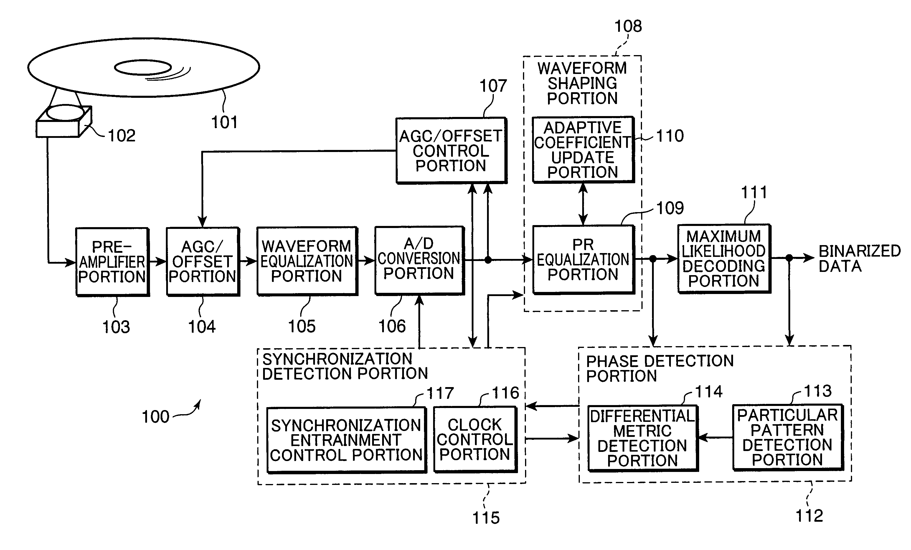
[0055]Initially, an optical disc device according to a first embodiment of the invention will be described. FIG. 6 is a block diagram showing the configuration of the optical disc device according to the first embodiment of the invention.

[0056]An information recording medium 101 is an information recording medium in and from which information is optically recorded and reproduced, and it is, for example, an optical disc.

[0057]The optical disc device 100 shown in FIG. 6 includes an optical head portion 102, a pre-amplifier portion 103, an AGC (Automatic Gain Controller) / OFFSET portion 104, a waveform equalization portion 105, an A / D conversion portion 106, an AGC / OFFSET control portion 107, a waveform shaping portion 108, a maximum likelihood decoding portion 111, a phase detection portion 112, and a synchronization detection portion 115. Further, the waveform shaping portion 108 includes a PR (Partial Response) equalization portion 109 and an adaptive coefficient update portion 110. ...

second embodiment

[0171]An optical disc device according to a second embodiment of the invention will be described first. FIG. 15 is a block diagram showing the configuration of the optical disc device according to the second embodiment of the invention.

[0172]The optical disc device of FIG. 15 is almost of the same configuration and operates almost in the same manner as the optical disc device of FIG. 6. Accordingly, only differences in configuration and operation from the optical disc device of FIG. 6 will be described herein.

[0173]In an optical disk device 200 shown in FIG. 15, the waveform shaping portion 108 includes a first adaptive coefficient update portion 110A and a second adaptive coefficient update portion 110B. The first adaptive coefficient update portion 110A updates the tap coefficients of the FIR filter in the PR equalization portion 109 using the LMS algorithm. The second adaptive coefficient update portion 110B updates the tap coefficients of the FIR filter in the PR equalization po...


PUM

PropertyMeasurementUnit
diameteraaaaaaaaaa
frequencyaaaaaaaaaa
physical lengthaaaaaaaaaa

Abstract

A waveform shaping portion receives a digital reproduced signal generated from an analog reproduced signal reproduced from an information recording medium and shapes the waveform of the digital reproduced signal. A maximum likelihood decoding portion applies maximum likelihood decoding to the digital reproduced signal in the shaped waveform and generates a binarized signal indicating the result of the maximum likelihood decoding. A phase detection portion extracts, during the maximum likelihood decoding, a phase error using state transition patterns having only a single zero cross point among differential metrics at a plurality of merging points at which a set of paths branched from a given state merges. A synchronization detection portion generates a reproduction clock signal using the phase error that has been detected and brings the digital reproduced signal into synchronization with the reproduction clock signal that has been generated. This configuration makes it possible to generate a reproduction clock signal in a stable manner.

Description

BACKGROUND OF THE INVENTION[0001]1. Field of the Invention[0002]The present invention relates to a phase error detecting device, a waveform shaping device, and an optical disc device for reproducing a signal recorded over the limit of optical resolution, and more particularly, to a phase error detecting device, a waveform shaping device, and an optical disc device for performing phase synchronization on a reproduced signal using maximum likelihood decoding, such as Viterbi decoding.[0003]2. Description of the Background Art[0004]Recently, the shortest mark length in recording is nearing the limit of optical resolution because of the density of an optical disc that is becoming higher and higher. An increase in intersymbol interference and deterioration of SNR (Signal Noise Rate) are therefore becoming more noticeable. Under these circumstances, it is becoming popular to adopt PRML (Partial Response Maximum Likelihood) as a signal processing method. PRML is a technique combining parti...

Claims


Application Information

Patent Timeline
Patent Type & Authority Patents(United States)
IPC IPC(8): G11B27/36
CPCG11B20/10009G11B20/10046G11B20/10222G11B20/10296G11B20/10481G11B2220/2541
Inventor MIYASHITA, HARUMITSUNAKATA, KOHEI
Owner PANASONIC CORP
Learn More