
Multi-element antenna

Inactive Publication Date: 2011-01-11
BAE SYSTEMS PLC
View PDF24 Cites 9 Cited by
  • Summary
  • Abstract
  • Description
  • Claims
  • Application Information

AI Technical Summary

Benefits of technology

[0005]Amongst the design constraints for a collision warning / avoidance system suitable for use with military jet aircraft in particular, are good directionality of the beams emitted by the antenna. This is to avoid unwanted emissions, for example in the backward direction relative to the direction of motion of the aircraft, which might interfere with other systems on board or give away the aircraft's presence or position. The antenna and associated switch array according to this first aspect of the present invention, particularly when used to generate sum and difference beams in a monopulse radar based system, offers particularly good directionality in comparison with prior art arrangements.
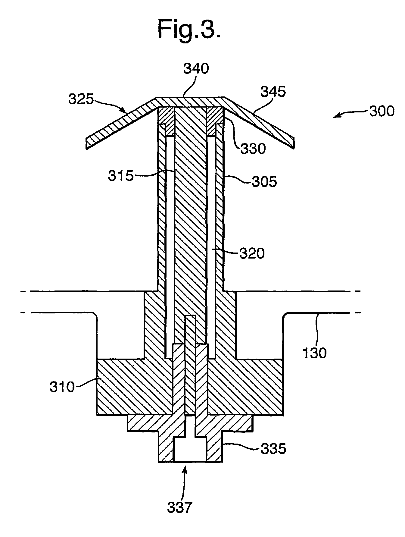
[0006]The use of top-loaded monopole antenna elements make for a particularly low-profile antenna. Moreover, the design of the antenna feed, in which a feed conductor is surrounded by a hollow cylindrical stem section, enables the input impedance of the antenna element to be set (e.g. to 50 Ohms) by appropriate dimensioning of the inner diameter of the stem section relative to the diameter of the feed conductor, thus forming a quarter-wave transformer. This has the advantage that an external matching transformer for each antenna element is avoided. Furthermore, the inventor in this case has noted that with this antenna element design, in which the top element is effectively fed at the top section of the “stem”, there is a slight improvement in the operational bandwidth of the antenna element in comparison with prior art designs.
[0008]Preferably, at least one of the plurality of antenna elements is a passive reflector element connected permanently to ground and positioned so as to increase the directionality of the antenna within the predetermined range of angles.

Problems solved by technology

Amongst the design constraints for a collision warning / avoidance system suitable for use with military jet aircraft in particular, are good directionality of the beams emitted by the antenna.

Method used


Image

  • Multi-element antenna
  • Multi-element antenna
  • Multi-element antenna

Examples


first embodiment

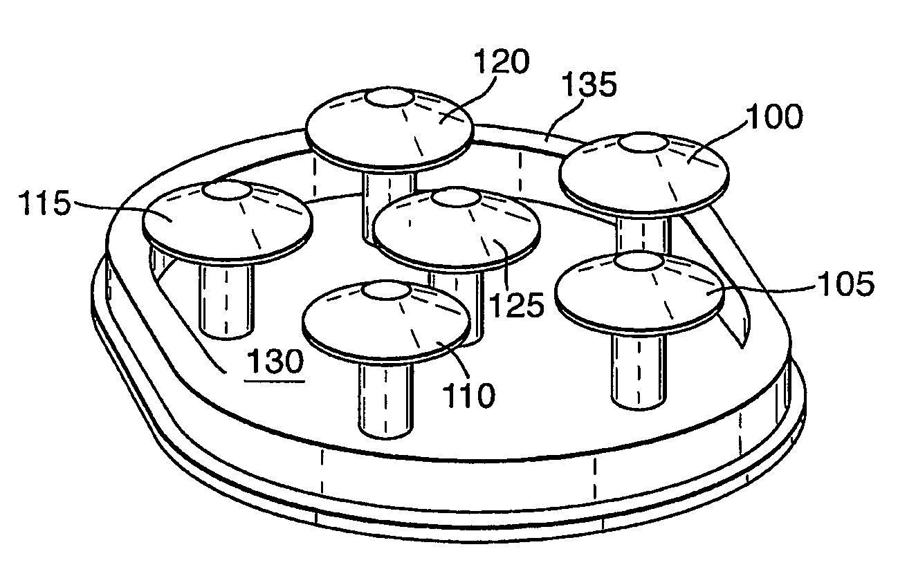
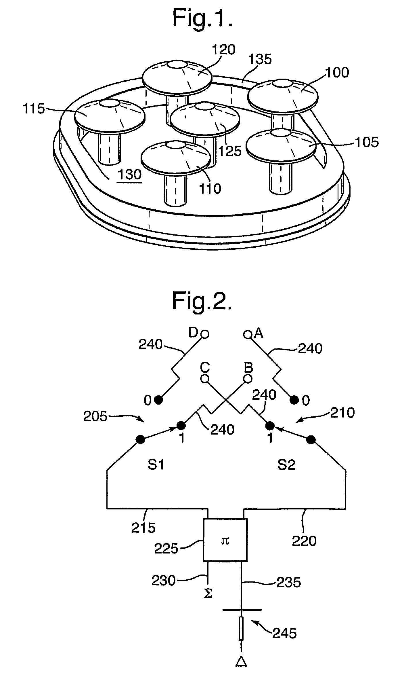
[0022]An antenna according to the present invention will now be described with reference to FIG. 1.

[0023]Referring to FIG. 1, the antenna comprises a pentagonal array of five antenna elements 100 to 120, surrounding a sixth central antenna element 125. The antenna elements 100-125 are mounted on an oval saddle plate 130 which incorporates a ground plane and which enables the antenna to be mounted conveniently on the outer skin of an aircraft fuselage or of another type of vehicle. A ridge 135 is provided around the saddle plate 130 for attachment of a radome (not shown in FIG. 1) to cover and protect the array of antenna elements 100-125. Alternatively, or in addition to a radome, the antenna elements 100-125 may be embedded in a dielectric foam or other dielectric material whose dielectric properties may be taken into account in the design of the antenna.

[0024]Each of the antenna elements 100-125 is a top-loaded monopole (TLM) antenna, selected in particular to minimise the overall...

second embodiment

[0044]The antenna according to this second embodiment of the present invention has the advantage of being a simpler design. However, the ratio of front-to-back coverage is reduced in comparison to the six element design of FIG. 1, being of the order of only 5 dB. This constraint in the performance of the antenna may be of lower significance in systems applied to vehicles or craft other than aircraft.


PUM


Abstract

An antenna is provided, in combination with an associated switch array, the antenna comprising a number of antenna elements mounted above a ground plane for providing coverage over a predetermined range of angles in azimuth using a number of beams. Each of the antenna elements is connected to a switch in the switch array and the switch array is operable to connect selected pairs of the antenna elements to a signal path to thereby generate each of the different beams, at the same time connecting unselected antenna elements to ground.

Description

CROSS-REFERENCE TO RELATED APPLICATIONS[0001]This application is a National Phase Application of PCT International Application No. PCT / GB2007 / 050727, International Filing Date 29 Nov. 2007; claiming priority of: GB Patent Application, 0625564.0, filed 21 Dec. 2006; GB Patent Application 0625557.4, filed 21 Dec. 2006; and EP Patent Application 06256461.2, filed 21 Dec. 2006, which are hereby incorporated by reference in their entirety.BACKGROUND OF THE INVENTION[0002]This invention relates to a multi-element antenna and in particular, but not exclusively, to a multi-element antenna and associated switching arrangement designed for use in a monopulse radar collision avoidance system.[0003]The Traffic alert and Collision Avoidance System (TCAS) is an implementation of the Airborne Collision Avoidance System which is fitted to all aircraft over a certain weight and / or passenger carrying capacity, as mandated by the International Civil Aviation Organisation. A recent implementation of TC...

Claims


Application Information

Patent Timeline
IPC IPC(8): H01Q3/24H01Q9/36H01Q25/02H01Q1/28H01Q9/00
CPCH01Q1/28H01Q3/24H01Q9/36H01Q25/02H01Q19/32
Inventor HENDERSON, ROBERT IAN
Owner BAE SYSTEMS PLC
Learn More