
Two-phase fast reroute with optimized traffic engineering

a traffic engineering and optimization technology, applied in the field of network communication, can solve the problems of slow rerouting process, and inability to optimize the traffic path of pre-computed backup tunnels, so as to minimize overall capacity or overall cost, optimize network resource usage, and maximize sharing

Active Publication Date: 2010-12-28
AMERICAN TELEPHONE & TELEGRAPH CO
View PDF8 Cites 49 Cited by
  • Summary
  • Abstract
  • Description
  • Claims
  • Application Information

AI Technical Summary

Benefits of technology

[0012]An optimized traffic engineering method is used to maximize sharing among all independent failure scenarios and also among different phases of restoration with the objective of minimizing overall capacity or overall cost. Further optimization of network resource usage may be achieved by allowing only a subset of the traffic classes (more important ones) to be restored during phase 1 of the fast reroute method. Embodiments allow for real-time sensitive IP services, such as IPTV, VoIP, gaming, and others to have a sub-100 ms failure restoration while maintaining efficient bandwidth utilization and efficient latency behavior of traffic flows. Following a failure event, the network is ready for efficient failure restoration for subsequent failures.

Problems solved by technology

This allows sub-100 ms restoration of traffic even though the pre-computed backup tunnel traffic path may not be optimal.
The rerouting process is relatively slow and may take several seconds.

Method used


Image

  • Two-phase fast reroute with optimized traffic engineering
  • Two-phase fast reroute with optimized traffic engineering
  • Two-phase fast reroute with optimized traffic engineering

Examples


Embodiment Construction

[0019]Embodiments of the invention will be described with reference to the accompanying drawing figures wherein like numbers represent like elements throughout. Before embodiments of the invention are explained in detail, it is to be understood that the invention is not limited in its application to the details of the examples set forth in the following description or illustrated in the figures. The invention is capable of other embodiments and of being practiced or carried out in a variety of applications and in various ways. Also, it is to be understood that the phraseology and terminology used herein is for the purpose of description and should not be regarded as limiting. The use of “including,”“comprising,” or “having,” and variations thereof herein is meant to encompass the items listed thereafter and equivalents thereof as well as additional items.

[0020]The terms “connected” and “coupled” are used broadly and encompass both direct and indirect connecting, and coupling. Furthe...


PUM


Abstract

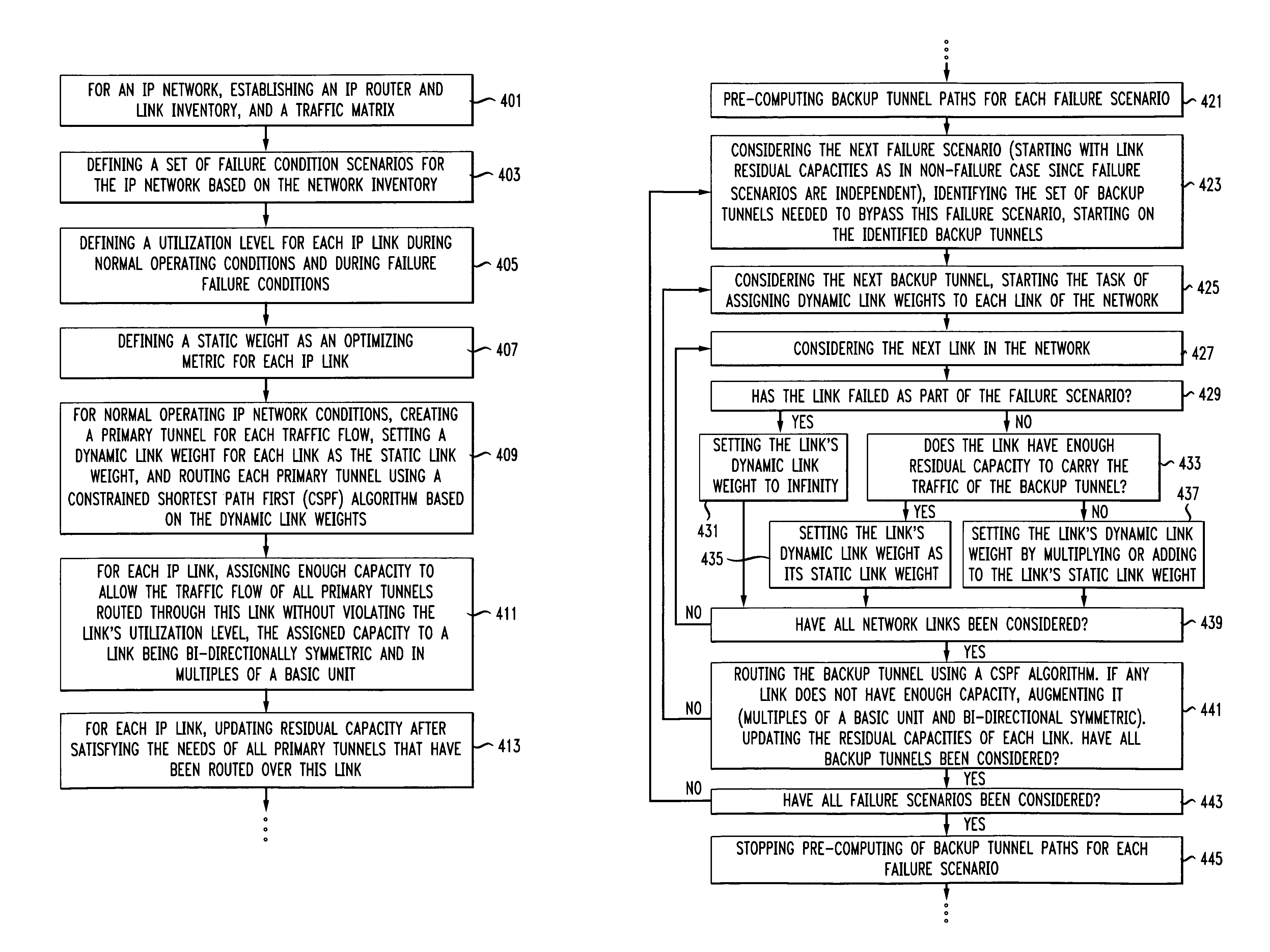
Systems and methods are described for restoring IP traffic flows routed in an IP network in less than 100 ms after the IP network sustains a network failure. The systems and methods are a two-phase fast reroute that uses distributed optimized traffic engineering during backup tunnel restoration and end-to-end tunnel restoration that maximizes sharing among all independent failure scenarios and minimizes the total capacity, total cost, or a linear combination of the two. For defined failure condition scenarios, restoration traffic is routed using pre-computed backup tunnels using a constrained shortest path first method where link weights along the path are chosen dynamically and depend on available and total capacity of the link, latency, and other cost measures such as IP port costs. During the capacity allocation phase, the method reuses capacity already allocated for other independent failure scenarios as much as possible but also adds capacity, if necessary. When an actual IP network failure occurs, the backup tunnels are used to immediately restore service to affected IP network traffic flows. In parallel, end-to-end tunnels corresponding to each affected traffic flow are rerouted and once the rerouting process is complete, traffic is switched over from the old end-to-end tunnel routes (using backup tunnels) to new end-to-end tunnel routes without using backup tunnels.

Description

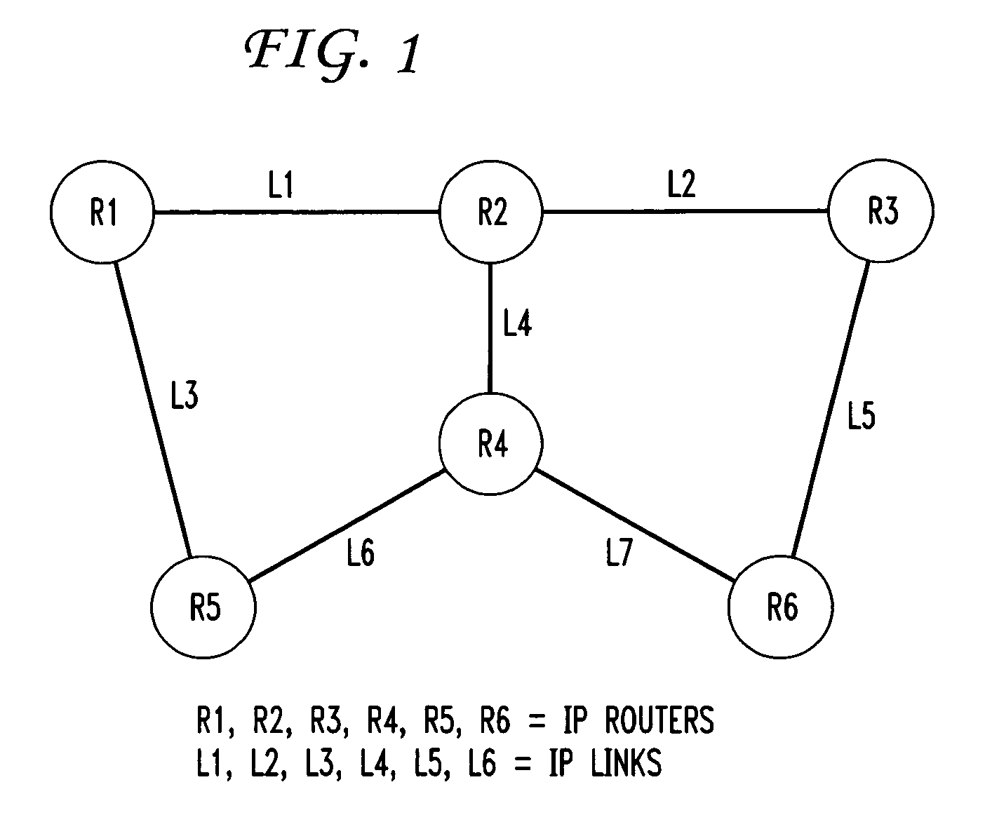
CROSS REFERENCE TO RELATED APPLICATIONS[0001]This application claims the benefit of U.S. Provisional Application No. 60 / 936,765, filed on Jun. 21, 2007, the disclosure which is incorporated herein by reference in its entirety.BACKGROUND OF THE INVENTION[0002]The invention relates generally to network communications. More specifically, the invention relates to systems and methods that optimize traffic engineering for restoring traffic in IP networks constructed over a variety of physical network architectures following IP Router failures, IP link failures; or a combination.[0003]FIG. 1 shows an exemplary IP network comprising six IP Routers and seven IP links. IP traffic may originate at any of the IP Routers and may travel to any of the other IP Routers over a sequence of one or more IP links. Each IP link may go over a sequence of Layer 1 links using a variety of technologies such as Gigabit Ethernet or Ultra Long Haul (ULH) technologies using Dense Wavelength Division Multiplexing...

Claims


Application Information

Patent Timeline
IPC IPC(8): G01R31/08H04L12/56H04B10/00G06F11/00G06F15/177G06F15/173H04J3/14H04J14/00H04L12/26H04L12/28
CPCH04L41/0681H04L45/00H04L45/125H04L45/22H04L45/28H04L41/0654H04L41/145H04L47/728
Inventor CHOUDHURY, GAGAN L.CHIU, ANGELA LANDOVERSPIKE, ROBERT DUNCANLI, GUANGZHI
Owner AMERICAN TELEPHONE & TELEGRAPH CO
Learn More