
Non-disruptive data migration with external virtualization engine

Active Publication Date: 2010-12-21
EMC IP HLDG CO LLC
View PDF21 Cites 29 Cited by
  • Summary
  • Abstract
  • Description
  • Claims
  • Application Information

AI Technical Summary

Benefits of technology

[0014]The system described herein allows for a single point of management for heterogeneous storage and may facilitate governmental compliance, which dictates that distributed storage assets be centrally controlled. The system may be used in connection with thin provisioning to maximize storage utilization. The system may facilitate data mirroring for business continuance. The system supports heterogeneous replication by allowing for transparent data migration across different storage platforms / tiers. The system may be used to provide Information Life Management (ILM) strategies, point-in-time snapshots, and be used to copy clone data for diverse uses. The system may provide the ability to integrate more storage into an overall storage pool without disruption and provide a consistent SCSI abstraction layer to the host, allowing for a common set of multi-path drivers and tools. The system may be used as a future platform for policy based storage compliance / automation and allow integration of Virtual Tape Library (VTL) capabilities. The system may use common encryption keys and facilitate heterogeneous data migration.

Problems solved by technology

However, since each port of each storage device has a unique identifier (e.g., WWPN), and since the zones are programmed into the switch(es) of the storage area network 20 using the unique identifiers, using a new storage device could require reprogramming all of the hosts coupled to the old storage device and / or could require adding new zones for the new storage device, one or both of which may be unacceptable.
For example, there may be instances where it is not acceptable to have any appreciable downtime of applications running on hosts.

Method used


Image

  • Non-disruptive data migration with external virtualization engine
  • Non-disruptive data migration with external virtualization engine
  • Non-disruptive data migration with external virtualization engine

Examples


Embodiment Construction

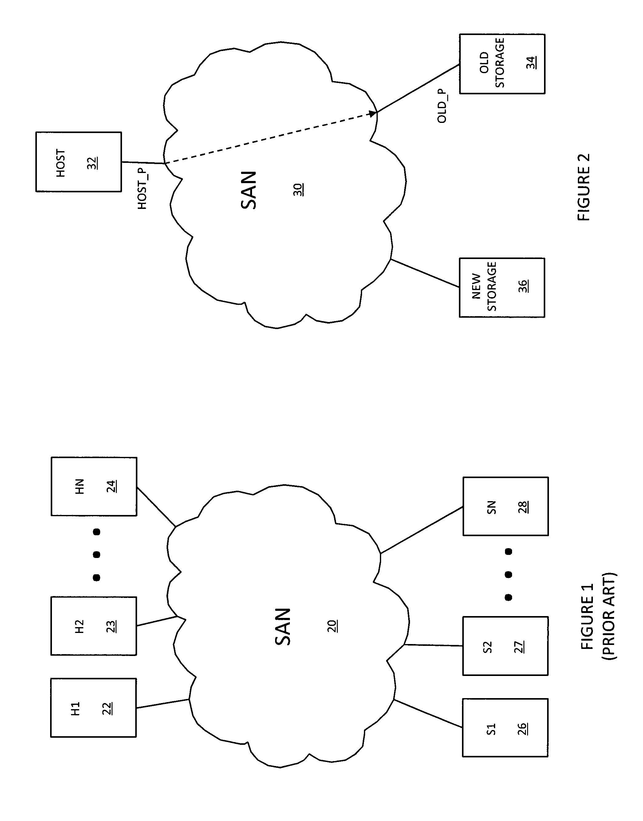
[0026]Referring to FIG. 2, a storage area network 30 is shown as having coupled thereto a host 32, an old storage device 34, and a new storage device 36. The storage area network 30 may be provided using any appropriate technology consistent with the description herein that can facilitate couplings between ports of devices. In an embodiment herein, the storage area network 30 may be provided using conventional Fibre Channel connectivity protocol and one or more switches. Of course, in other embodiments, the storage area network 30 may provide coupling using other appropriate connectivity protocols and / or switch technology consistent with the description herein.

[0027]Note that the storage area network 30 is illustrated in FIG. 2 with only a single host and two storage devices, but the system described herein may be implemented for systems having any number of hosts and any number of storage devices coupled to the storage area network of 30. Note also that the host 32 should be unders...


PUM


Abstract

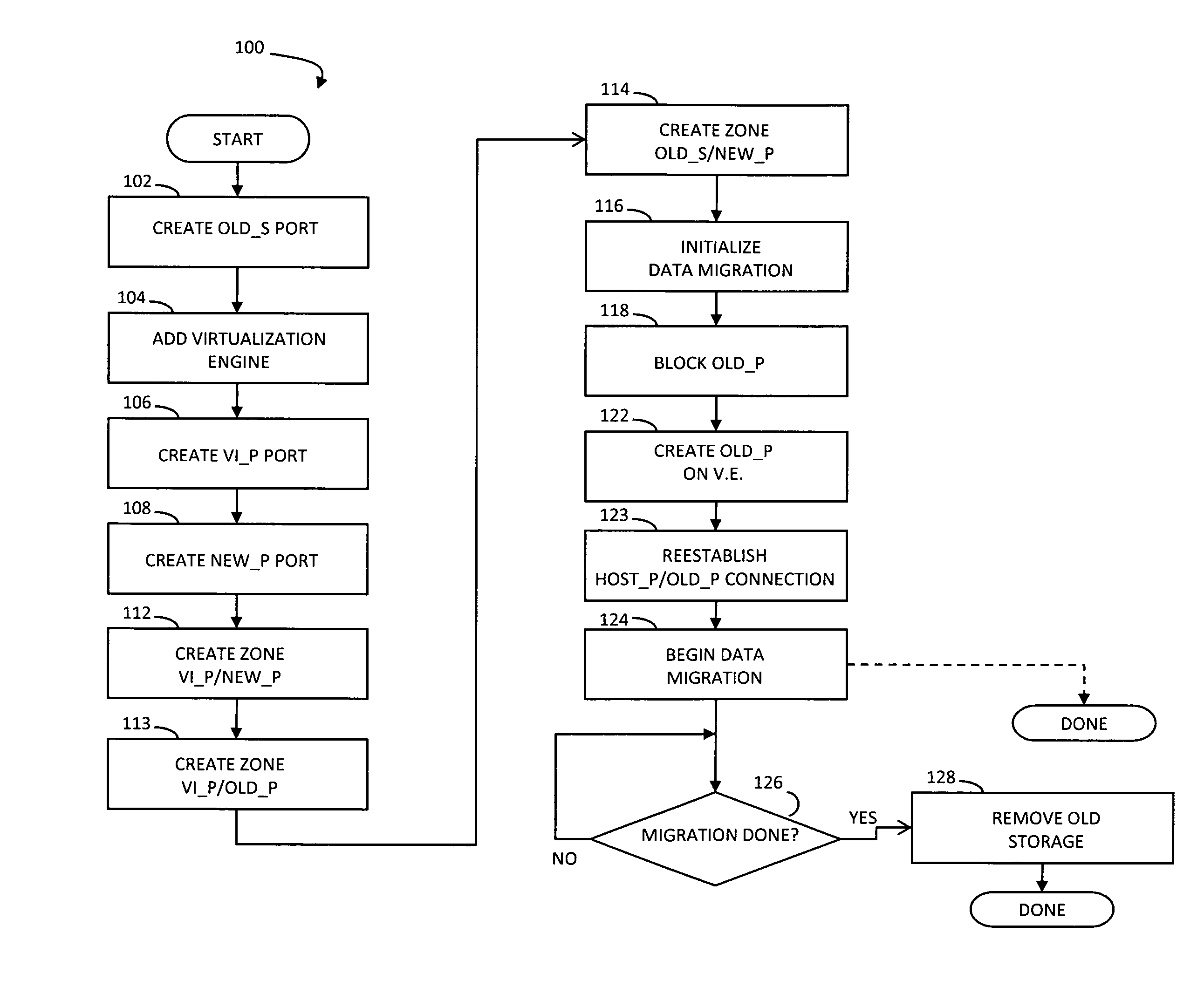
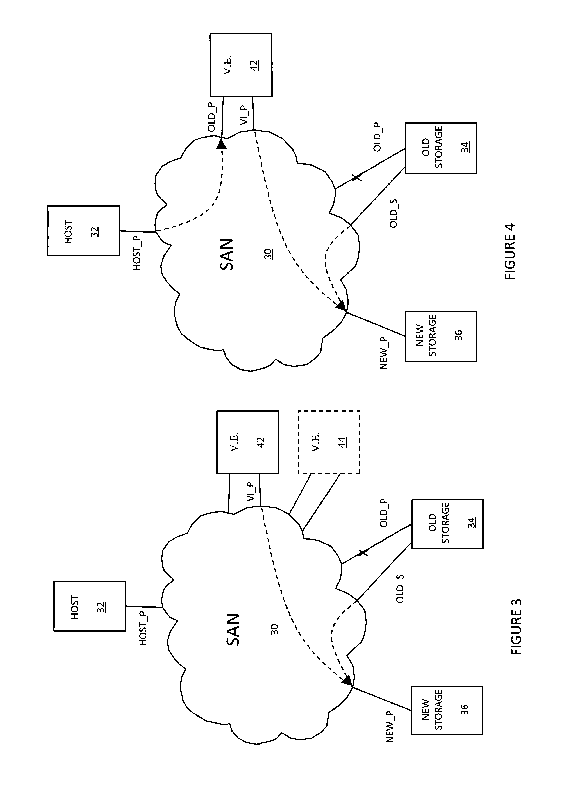
Transferring I / O from a first storage device coupled to a storage area network to a second storage device coupled to the storage area network includes blocking I / O operations for a first port of the first storage device coupled to the storage area network, where the first port is associated with a first identifier. Transferring I / O also includes coupling the second storage device to the storage area network via a port associated with a second identifier different from the first identifier, coupling a virtualization engine to the storage area network via a first port provided with the first identifier and via a second port, and causing at least a portion of I / O operations received by the virtualization engine through the first port thereof to be routed through the second port thereof to the second storage device without host / application disruption.

Description

BACKGROUND OF THE INVENTION[0001]1. Technical Field[0002]This application relates to computer storage devices, and more particularly to the field of migrating data between storage devices coupled to a network.[0003]2. Description of Related Art[0004]A storage area network may be used to couple one or more host devices with one or more storage devices in a manner that allows reconfiguring connections without having to physically disconnect and reconnect cables from and to ports of the devices. A storage area network may be implemented using one or more switches to which the storage devices and the host devices are coupled. The storage area network may be essentially transparent to the devices so that the devices operate in a manner identical or similar to their operation when directly connected to each other. The switches may be programmed to allow connections between specific ports of devices coupled to the switches. A port that can initiate a data-path connection is called an “init...

Claims


Application Information

Patent Timeline
IPC IPC(8): H04L12/28H04L12/56
CPCG06F3/0604G06F3/0647G06F3/067H04L67/1097
Inventor WIGMORE, IAN
Owner EMC IP HLDG CO LLC
Learn More