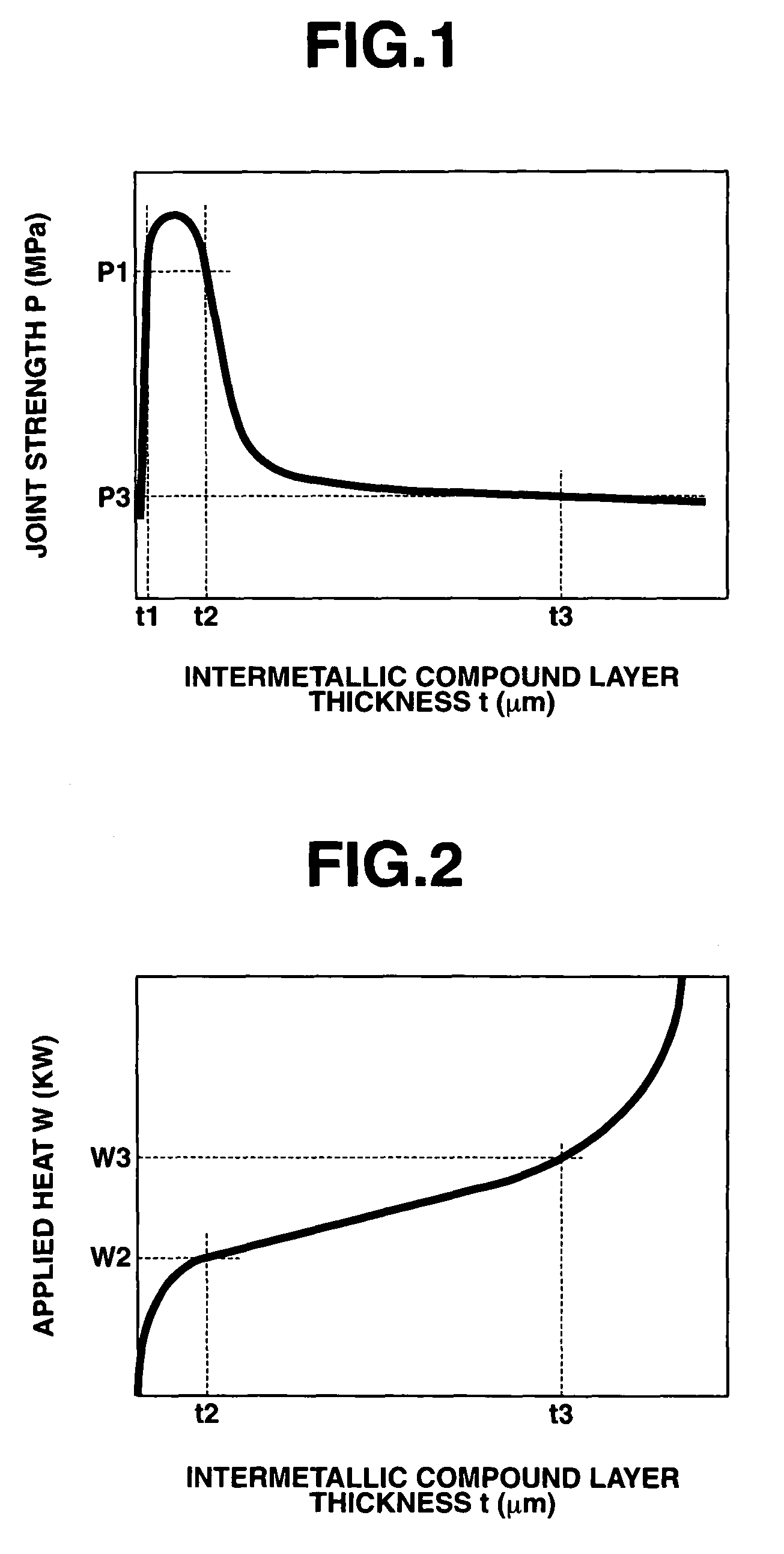
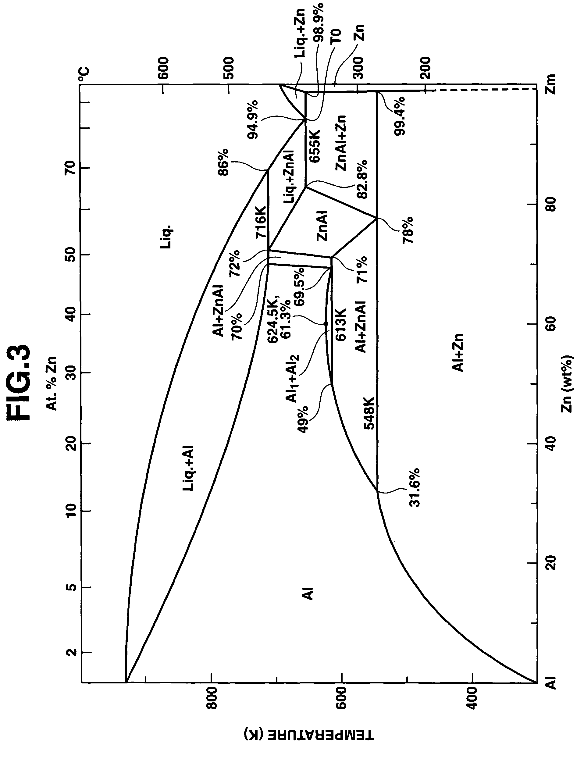
Dissimilar metal joining method
a metal joining and dissimilar technology, applied in the direction of non-electric welding apparatus, manufacturing tools, welding apparatus, etc., can solve the problems of difficult production of clad metal material, formation of fragile intermetallic compounds between, and difficulty in practical us
- Summary
- Abstract
- Description
- Claims
- Application Information
AI Technical Summary
Benefits of technology
Problems solved by technology
Method used
Image
Examples
first embodiment
[0032]A metal joining process of the first embodiment will be now described below in detail with reference to FIGS. 4A to 4E.
[0033]A steel sheet 1 (as the first metal material) with a zinc plating 3 (as the third metal material) and an aluminum alloy sheet 2 (as the second metal material) are first prepared as shown in FIG. 4A. The steel sheet 1 is a cold-reduced carbon steel sheet SPCC according to JIS G 3141 and has a thickness of 0.55 mm and a width of 3 mm. The zinc plating 3 has a thickness of 6 μm. For process simplification and efficiency improvement, a commonly-available, rust-proof zinc plated steel material sheet SGCC according to JIS G 3302 is used as a laminated composite in which the zinc plating 3 has previously been applied to a clean surface of the steel sheet 1 in the first embodiment. The aluminum alloy sheet 2 is a 6000-series aluminum alloy sheet comprising aluminum, 1.0% of silicon and 0.6% of magnesium according to JIS H 4000 and has a thickness of 1 mm and a w...
second embodiment
[0040]As shown in FIG. 5A, a steel sheet 1 (as the first metal material) with a zinc plating 3 (as the third metal material) and an aluminum alloy sheet 2 (as the second metal material) are first prepared. The steel sheet 1 is a cold-reduced carbon steel sheet SPCC according to JIS G 3141 and has a thickness of 0.55 mm and a width of 3 mm. The zinc plating 3 has a thickness of 20 μm. A commonly-available, rust-proof zinc plated steel material sheet SGCC according to JIS G 3302 is also used as a laminated composite in which the zinc plating 3 has previously been applied to a clean surface of the steel sheet 1 in the second embodiment for process simplification and efficiency improvement. The aluminum alloy sheet 2 is a 6000-series aluminum alloy sheet comprising aluminum, 1.0% of silicon and 0.6% of magnesium according to JIS H 4000 and has a thickness of 1 mm and a width of 10 mm. An oxide film 4 is formed in a surface of the aluminum alloy sheet 2. The laminate of the steel sheet 1...
third embodiment
[0047]The laser spot welding is performed by irradiating a high-energy beam from one material side to form a spot of the high-energy beam on either of the first and second metal materials in the
[0048]It is herein preferable during the irradiation of the high-energy beam to exert a pressure on the metal material at a position around the beam spot in such a manner as to press the first and second metal materials against each other and bring the oxide film into intimate contact with the third metal material. When the metal materials are held in intimate contact with each other, the oxide film is more likely to be broken or ruptured by the frictional displacement between the metal materials due to thermal expansion under the irradiation of the high-energy beam. The eutectic melting is thus promoted effectively upon the occurrence of such a break or rupture of the oxide film. This makes it possible to control the joint interface temperature to a relatively low temperature so as to limit ...
PUM
| Property | Measurement | Unit |
|---|---|---|
| thickness | aaaaa | aaaaa |
| melting point | aaaaa | aaaaa |
| melting point | aaaaa | aaaaa |
Abstract
Description
Claims
Application Information
 - R&D
- Intellectual Property
- Life Sciences
- Materials
- Tech Scout
- Unparalleled Data Quality
- Higher Quality Content
- 60% Fewer Hallucinations
Browse by: Latest US Patents, China's latest patents, Technical Efficacy Thesaurus, Application Domain, Technology Topic, Popular Technical Reports.
© 2025 PatSnap. All rights reserved.Legal|Privacy policy|Modern Slavery Act Transparency Statement|Sitemap|About US| Contact US: help@patsnap.com


