
Image forming apparatus

a technology of image forming and forming drums, applied in the direction of electrographic process apparatus, instruments, optics, etc., can solve the problems of increasing the abrasion loss the surface potential of the photosensitive drum may not be uniform, and the life of the photosensitive drum is short, so as to reduce the scattering of toner and achieve the effect of appropriate image quality

Inactive Publication Date: 2010-12-07
CANON KK
View PDF14 Cites 5 Cited by
  • Summary
  • Abstract
  • Description
  • Claims
  • Application Information

AI Technical Summary

Benefits of technology

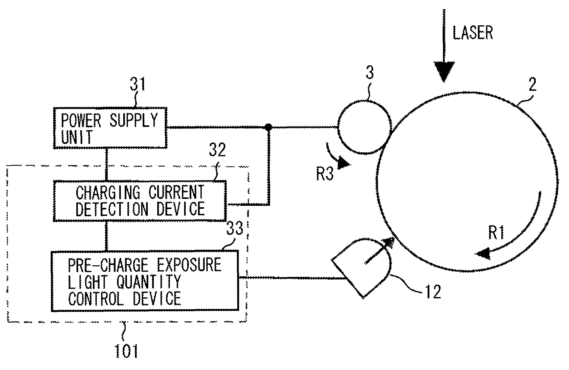
The present invention relates to an image forming apparatus that can determine the optimal light quantity for a pre-charge exposure device without using a surface potential detection device. Additionally, the invention aims to reduce toner scattering while preventing ghost image formation and maintaining good image quality regardless of variations in the use of the electrophotographic photosensitive member, contact charging member, and pre-charge exposure device. The image forming apparatus includes a rotatable electrophotographic photosensitive member, a contact charging member, a charging current detection device, a pre-charge exposure device, a standard exposure device, and a control device. The control device controls the charging current detection device to detect the current value that flows through the contact charging member when the rotatable electrophotographic photosensitive member is exposed by either the standard exposure device or the pre-charge exposure device, and the light quantity of the pre-charge exposure device is determined based on the detected current value.

Problems solved by technology

However, in the AC superposition system, electrical discharge occurs in a micro gap between the contact charging member and the photosensitive drum, which shortens a life of the photosensitive drum.
This is because the discharge causes damage to the photosensitive drum surface and increases abrasion loss of the photosensitive drum.
However, there have been the following problems in charging the photosensitive drum particularly with the DC system.
After an image is formed, a surface potential of the photosensitive drum may not be uniform due to an image pattern that has been formed on the surface.
As a result, the surface potential of the photosensitive drum becomes non-uniform when the photosensitive drum surface is exposed to a laser beam by the image exposure device next time.
However, if the photosensitive drum is uniformly irradiated by the pre-charge exposure device and the surface potential of the photosensitive drum becomes completely uniform, a problem of scatter of the residual transfer toner arises.
If the light quantity of the pre-charge exposure device decreases, a vestige of the previously-formed image may not be successfully deleted and may result in the formation of ghost image.
However, since the surface potential detection device is expensive, employment of the surface potential detection device is not desirable from the viewpoint of providing an inexpensive image forming apparatus.
However, it is difficult to estimate a change in the light quantity of the pre-charge exposure device occurring due to variations in manufacturing and the wear caused through the long time use, and adjust the light quantity of the pre-charge exposure device.
However, when the light quantity is precisely adjusted, manufacturing efficiency will be lowered which will result in increased cost.
Further, if the light quantity of the pre-charge exposure device is reduced due to the long time use or stain on the pre-charge exposure device caused by a user, the ghost image is formed on the drum.
Furthermore, individual variation of the contact charging member or variation in resistance value according to a use environment may cause a difference in charge current value which leads to insufficient detection accuracy.

Method used


Image

  • Image forming apparatus
  • Image forming apparatus
  • Image forming apparatus

Examples


Embodiment Construction

[0032]Various exemplary embodiments, features, and aspects of the invention will be described in detail below with reference to the drawings.

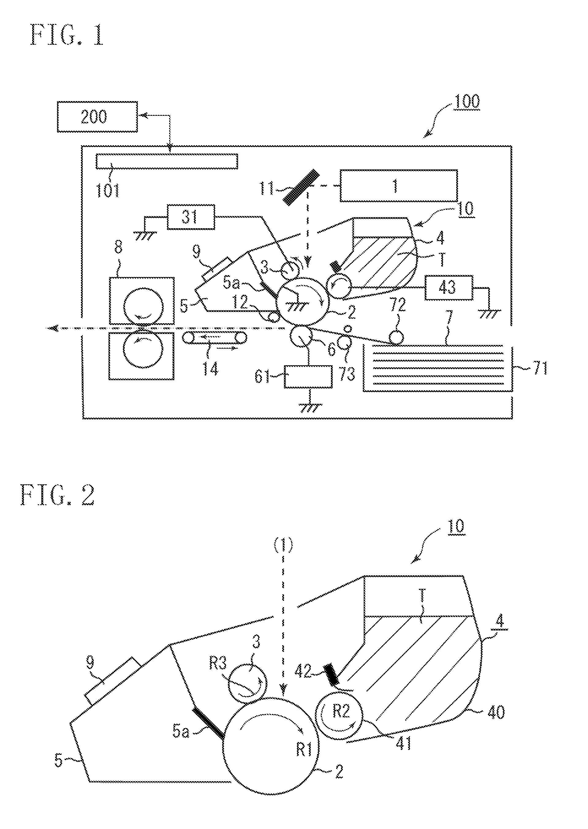
[0033]FIG. 1 illustrates a configuration of an image forming apparatus according to a first exemplary embodiment of the present invention.

[0034]The image forming apparatus according to the present exemplary embodiment is an electrophotographic printer configured to perform a series of image forming processes including charging, exposing, developing, transferring, and cleaning with respect to a rotatable electrophotographic photosensitive member to form an image on a transfer material.

[0035]An image is formed on a transfer material (recording medium). The image corresponds to an electric image signal input from an external host apparatus 200, such as a personal computer, to a control device (engine controller) 101 of an image forming apparatus 100. The control device 101 exchanges various information with the external host apparatus 200 and make...


PUM


Abstract

An image forming apparatus includes a standard exposure device (1) adjusted to emit light of a predetermined light quantity, and a control device configured to determine light quantity of the pre-charge exposure device in an image-forming period based on the first and the second charging current values, wherein first charging current value is detected when an area on a photosensitive member surface is recharged by the contact charging member, in a case where the photosensitive member is exposed by turning on the standard exposure device without turning on a pre-charge exposure device, and second charging current value is detected when an area on the photosensitive member surface is recharged by the contact charging member, in a case where the photosensitive member charged by applying a predetermined voltage by the contact charging member is exposed by turning on the pre-charge exposure device without turning on the standard exposure device.

Description

BACKGROUND OF THE INVENTION[0001]1. Field of the Invention[0002]The present invention relates to an image forming apparatus employing an electrophotographic method.[0003]2. Description of the Related Art[0004]Conventionally, image forming apparatuses are known that employ an electrophotographic method, such as an electrophotographic copier, an electrophotographic printer (e.g., light-emitting diode (LED) printer, laser beam printer, etc.), and an electrophotographic facsimile machine.[0005]The image forming apparatus of this type includes a charging device which uniformly charges a surface of an electrophotographic photosensitive member and an image exposure device which exposes the charged surface of the electrophotographic photosensitive member to light to form an electrostatic latent image. The electrophotographic photosensitive member is drum-shaped or endless-belt-shaped and can be rotated at a predetermined speed. The electrophotographic photosensitive member used in electroph...

Claims


Application Information

Patent Timeline
Patent Type & Authority Patents(United States)
IPC IPC(8): G03G21/00
CPCG03G15/0266G03G21/08
Inventor KANAI, RYOSUKEKISHI, YOSUKE
Owner CANON KK
Learn More