Image-Forming Apparatus
a technology of image-carrying belts and electrode plates, which is applied in the direction of electrographic process apparatus, instruments, optics, etc., can solve the problems of inability to regulate the inability to form the desired electric field between the image-carrying belt and the electrode plate, etc., and achieve the effect of reducing the scattering of toner
- Summary
- Abstract
- Description
- Claims
- Application Information
AI Technical Summary
Benefits of technology
Problems solved by technology
Method used
Image

Examples
first exemplary embodiment
[0029] First Exemplary Embodiment
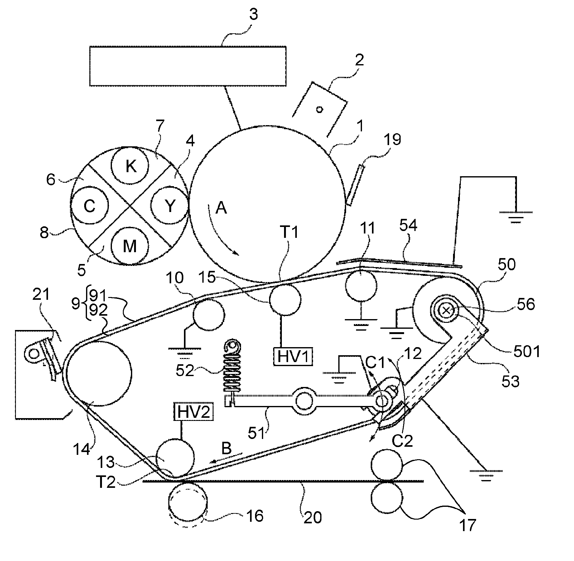
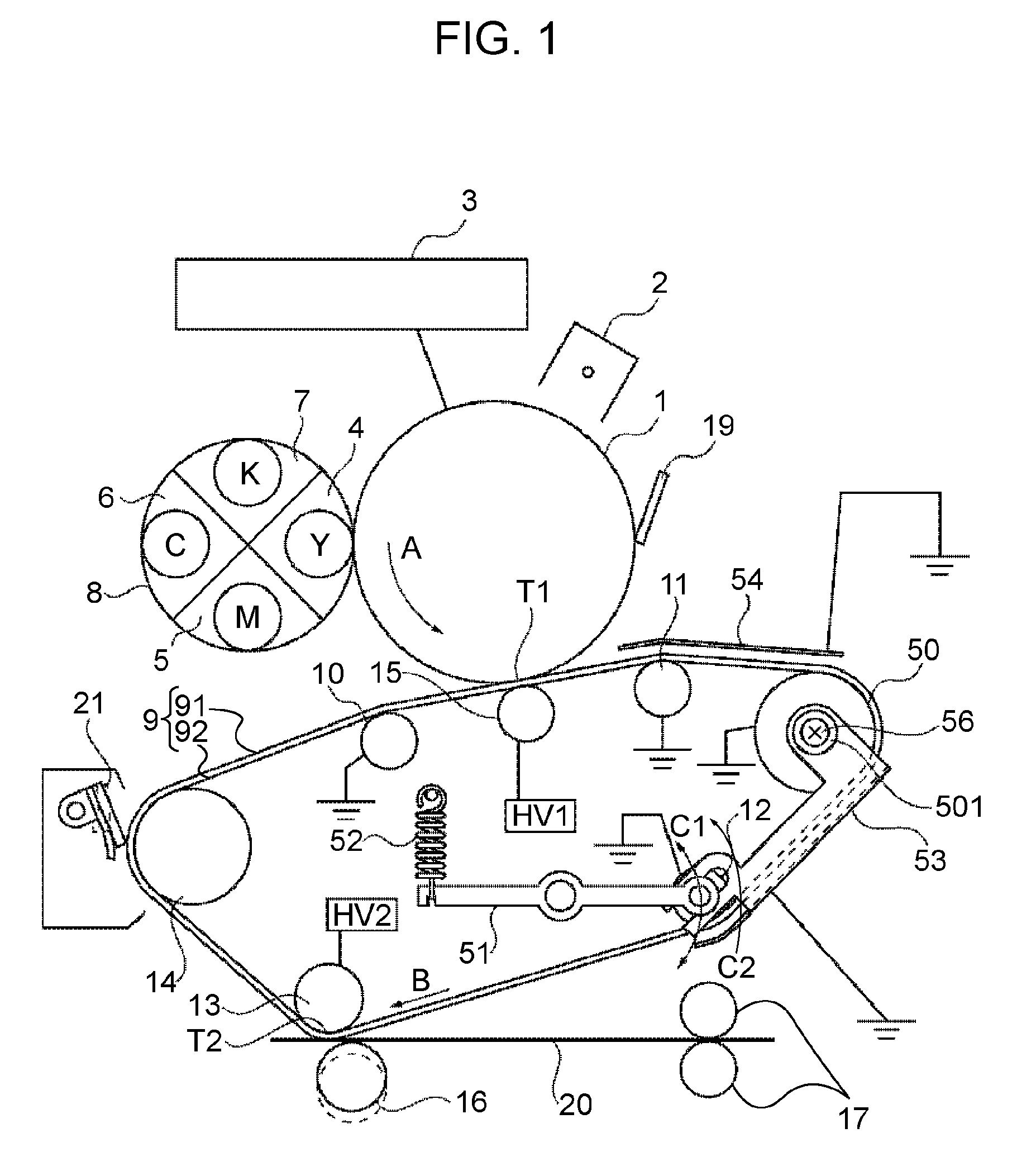
[0030]FIG. 1 illustrates a schematic structure of a color-image-forming apparatus to which the present invention is applied.
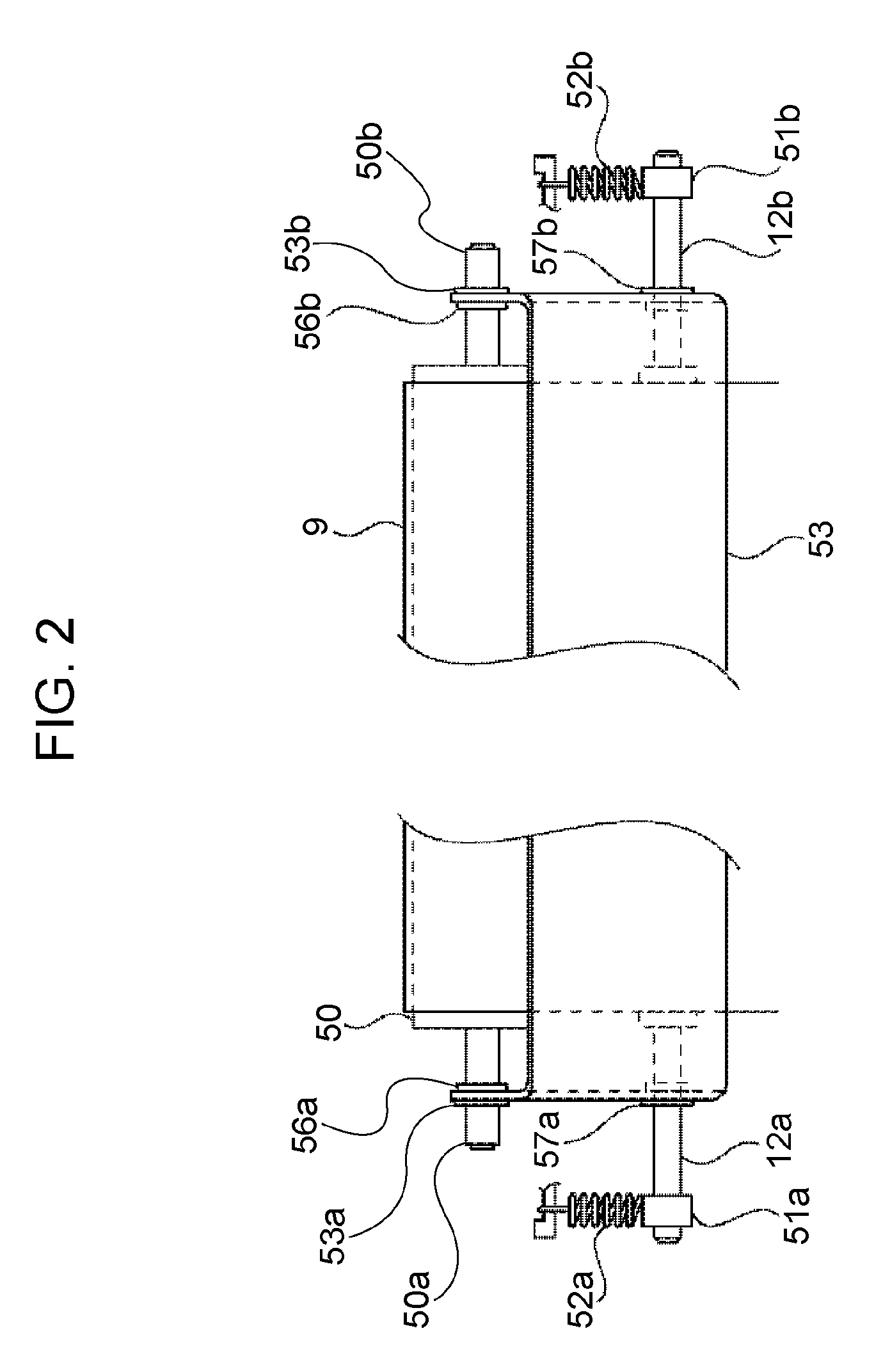
[0031]FIG. 2 illustrates an intermediate transfer belt 9 (described below) and a roller 12 that supports the intermediate transfer belt 9 in detail. The image-forming apparatus according to this exemplary embodiment will now be described with reference to FIGS. 1 and 2.
[0032] A photosensitive drum (image carrier) 1 rotates in the direction of an arrow A shown in FIG. 1, and the surface thereof is negatively charged in a uniform manner by an electrifying unit 2 during the rotation of the photosensitive drum 1. The charged photosensitive drum 1 is exposed to light by an exposing unit 3 that performs exposure on the basis of image information such that electrostatic images corresponding to the image information are formed.
[0033] A developing unit 8 including developing devices 4 to 7 corresponding to colors of yellow (Y), magent...
second exemplary embodiment
[0085] Second Exemplary Embodiment
[0086] The rollers 11, 50, and 12 shown in FIG. 1 are grounded. In contrast, a bias (+1 to +3 kV) having a polarity opposite to that of the toner is applied to the rollers of the image-forming apparatus according to this exemplary embodiment shown in FIG. 8 by a power supply HV3.
[0087] When a bias is applied to the extension roller 11, the potential of the intermediate transfer belt 9 is also raised. However, the potential difference between the extension roller 11 and the intermediate transfer belt 9 can be further reduced due to the potential-controlling plate 54.
[0088] Thus, the electric field intensity in the vicinity of the contact portion of the intermediate transfer belt 9 and the extension roller 11 can also be further reduced, and toner scattering can be effectively prevented.
[0089] Therefore, as shown in FIGS. 8 and 9, the potential-controlling plate 53 according to the second exemplary embodiment of the present invention is attached to...
PUM
 Abstract
Description
Claims
Application Information
 - R&D
- Intellectual Property
- Life Sciences
- Materials
- Tech Scout
- Unparalleled Data Quality
- Higher Quality Content
- 60% Fewer Hallucinations
Browse by: Latest US Patents, China's latest patents, Technical Efficacy Thesaurus, Application Domain, Technology Topic, Popular Technical Reports.
© 2025 PatSnap. All rights reserved.Legal|Privacy policy|Modern Slavery Act Transparency Statement|Sitemap|About US| Contact US: help@patsnap.com