Hydrodynamic bearing device, and spindle motor and information device using the same

a technology of hydrodynamic bearings and information devices, which is applied in the direction of sliding contact bearings, mechanical energy handling, mechanical equipment, etc., can solve the problems of reducing torque, affecting the performance of the record/record head, and accumulating electric charge within, so as to promote conductivity, reduce the effect of volume resistance, and facilitate the effect of conductivity

Inactive Publication Date: 2010-12-07
PHC HLDG CORP
View PDF18 Cites 1 Cited by
  • Summary
  • Abstract
  • Description
  • Claims
  • Application Information

AI Technical Summary

Benefits of technology

[0019]The present invention makes it possible for the lubricant to exhibit favorable conductivity (low volume resistivity) without the addition of additives that promote conductivity and / or that have an antistatic effect, so that a hydrodynamic bearing device with high reliability can be achieved. In addition, said hydrodynamic bearing device can be designed to exhibit reduced torque while avoiding any increased viscosity of the lubricant that is due to such additives. Furthermore, since lubricant is superior in performance balance such that the viscosity and the changes of temperature in viscosity of the lubricant is low, and the heat resistance and the hydrolysis stability is high, low-temperature fluidity is improved, and the like relative to conventional systems, so that a hydrodynamic bearing device with high reliability can be achieved. With these results, a hydrodynamic bearing device with low power consumption, small temperature change for electric power and a long operational lifetime, which makes it possible to use under cryogenic environments, can be achieved. Moreover, the amount of lubricant used to fill each hydrodynamic bearing device unit can be reduced, so that cost will be reduced and it will be possible to miniaturize the device.

Problems solved by technology

However, in the particular case of a spindle motor equipped with this type of hydrodynamic bearing device used in magnetic disk devices, an electrostatic charge is generated by the flow of the lubricant that is interposed between the shaft and the sleeve and the air friction of the magnetic disk due to the high-speed rotation without contact between the sleeve and the shaft of the hydrodynamic bearing device, and this electric charge will be accumulated within the device.
This accumulated electric charge can be discharged between the magnetic disk connected either to the shaft or the sleeve and the record / replay head, raising a concern about record / replay failures or damage to the record / replay head.
The use of low viscosity lubricants can also result in reduced torque (in other words, low power consumption).
However, there are problems with these conventional devices as follows.
The viscosity of the lubricant will rise after adding more than a certain amount of a high molecular weight or a high viscosity compound as an additive in order to increase the conductivity or antistatic effect, which leads to the problem of increased torque in the bearing device (in other words, increasing the power consumption).
Furthermore, as the additive undergoes degradation, the reduced effectiveness of the additive can cause a progressive degradation of the entire lubricant, leading to the problem that long-term reliability cannot be achieved for the device.
Further, while it is possible to reduce the torque in such conventional hydrodynamic bearing devices using the low viscosity lubricant, since the heat resistance of the lubricant is low (vapor pressure is high), the amount of evaporation will be significant when used over a long period, and it will not be possible to maintain the quantity of lubricant required for stabilized rotation of the bearing device.
Consequently, there will be problems with the device having inadequate reliability and the operational lifetime will be shorter.
However, this approach will entail problems in that this additional amount can increase the torque and bring a higher cost, and accommodating the additional space will make miniaturization more difficult.
Moreover, with conventional hydrodynamic bearing device where the lubricant with low-pour point is used, while it is possible to work at low temperature since changes of temperature in viscosity is large (in other words, viscosity index is small), there is the problem of increasing the power consumption at low temperature.
Also, especially with the hydrodynamic bearing device where the dicorboxylic acid diester base lubricant is used, pyrolysis temperature is low and stability for hydrolysis is small, which leads to the problem that long-term reliability cannot be achieved for the device under a condition such as high temperatures and humidity.

Method used


Image

  • Hydrodynamic bearing device, and spindle motor and information device using the same
  • Hydrodynamic bearing device, and spindle motor and information device using the same
  • Hydrodynamic bearing device, and spindle motor and information device using the same

Examples


embodiment 1

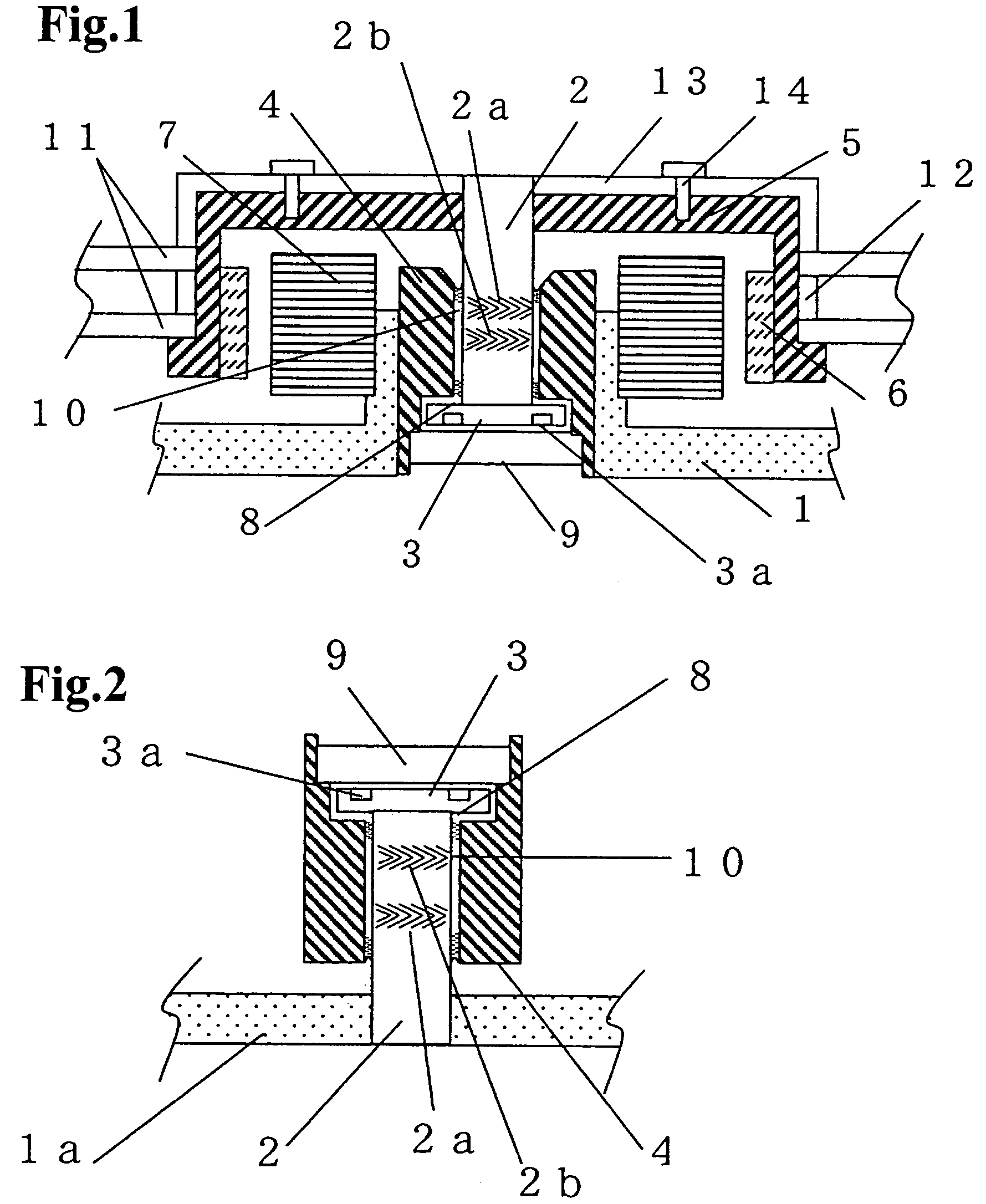
[0025]Embodiment 1 of the present invention is described with reference to FIG. 2. FIG. 2 is a cross section drawing of the main component for a hydrodynamic bearing device in a fixed shaft type of Embodiment 1.

[0026]In FIG. 2, radial dynamic pressure-generating grooves 2a and 2b are formed in a herringbone pattern on the outer circumferential surface of shaft 2. One end of the shaft 2 is affixed to thrust flange 3, and the other end is press fitted into base 1a. Shaft 2 and thrust flange 3 form the shaft component. In the present invention, only the shaft 2 may constitute a shaft structure, and optionally, a part (FIG. 3) or all of the thrust flange 3 (FIG. 1 and FIG. 2) and the hub 15 may constitute the shaft structure. The shaft component and the base 1a constitute the fixed component.

[0027]On the one hand, sleeve 4 possesses a bearing bore that supports the shaft component. Thrust plate 9 is mounted on one end of sleeve 4. The shaft component is inserted into the bearing bore of...

embodiment 2

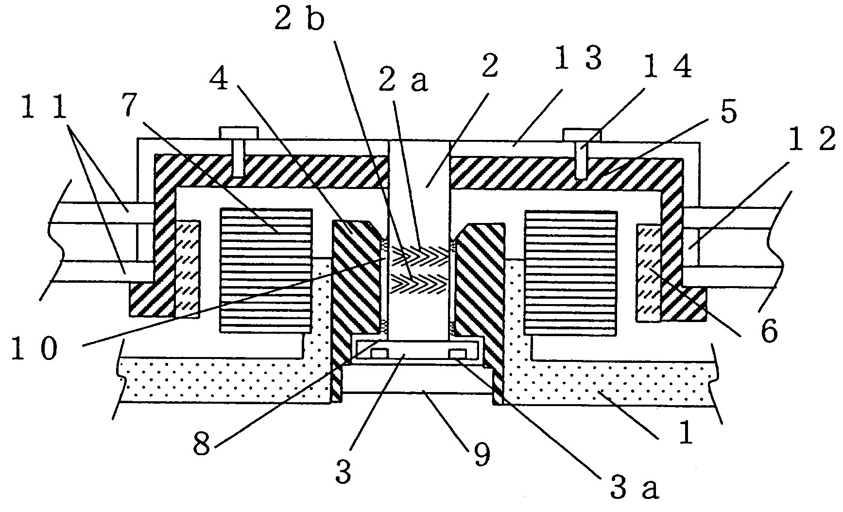
[0041]Embodiment 2 of the present invention is explained by using FIG. 1. FIG. 1 is a cross section drawing of the main component of a magnetic disk device equipped with a spindle motor that possesses a rotating shaft-type hydrodynamic bearing device of Embodiment 2. The hydrodynamic bearing device in this Embodiment differs from the hydrodynamic bearing device in Embodiment 1 in FIG. 2 in the point that the present Embodiment has a rotating shaft type while Embodiment 1 has a fixed shaft type, and has the thrust dynamic pressure-generating grooves such as a herringbone pattern. With the exception of this point, Embodiment 2 is identical to Embodiment 1, and any of the elements having identical symbols have been omitted from the explanation.

[0042]In FIG. 1, radial dynamic pressure-generating grooves 2a and 2b are formed in a herringbone pattern on the outer circumferential surface of shaft 2, and the one end of shaft is affixed to thrust flange 3, and the other end is press fitted i...

embodiment 3

[0047]FIG. 3 is a cross section drawing of the main component of a magnetic disk device equipped with a spindle motor that possesses a rotating shaft-type hydrodynamic bearing device.

[0048]In this magnetic disk device, a sleeve 21 that pressure fitted into the center of base 31 possessed a bearing bore that bears the shaft 22. Stator coil 17 is mounted on a wall formed by the base 31. The shaft 22 is inserted into the bearing bore of sleeve 21 from one end and the other end of the bearing bore is closed over by a cap 21a. Radial dynamic pressure-generating grooves (not shown) are formed in a herringbone pattern on the outer circumferential surface of shaft 22, and the one end of shaft 22 is press fitted into hub 15 as well as the other end of shaft 22 is opposed to the cap 21a. The outer circumferential surface of the shaft 22 (a dynamic-pressure surface) radially oppose to the inner circumferential surface of the sleeve 21 (a dynamic-pressure surface) interposed a gap R therebetwee...


PUM

PropertyMeasurementUnit
temperatureaaaaaaaaaa
volume resistivityaaaaaaaaaa
temperatureaaaaaaaaaa

Abstract

A hydrodynamic bearing device, comprising a shaft structure, a sleeve, a dynamic pressure-generating groove which is formed on surface of at least one of a shaft structure and a sleeve, and a lubricant present in a gap between the shaft structure and the sleeve; wherein the lubricant contains a diester with a total carbon number of 20 to 28 obtainable by a divalent alcohol that has three ether bond, and one or more types of a saturated monovalent fatty acid with carbon number of 6 to 10.

Description

BACKGROUND OF THE INVENTION[0001]1. Field of the Invention[0002]The present invention relates to a dynamic pressure-type hydrodynamic bearing device, as well as a spindle motor and information device using the same.[0003]2. Description of the Prior Art[0004]A hydrodynamic bearing device comprises a shaft and a sleeve that supports the shaft, and a lubricant that is interposed in the gap between the two parts. With rotation of the shaft, the lubricant is gathered up by dynamic pressure-generating grooves that are formed on the shaft or sleeve, and generate pressure such that the shaft is supported within the sleeve without coming into contact therewith. As a result, when high-speed rotation is attained, ambient noise during the rotation can be alleviated.[0005]A spindle motor equipped with such a hydrodynamic bearing device can provide the requisite rotational accuracy with an increased recording density of the medium, and can furthermore provide excellent shock resistance and quietn...

Claims


Application Information

Patent Timeline
Patent Type & Authority Patents(United States)
IPC IPC(8): C10M105/38F16C33/10
CPCC10M105/38C10M107/34F16C17/107F16C33/109C10M2207/026C10M2207/2835C10M2209/1055C10M2209/1065C10N2220/00C10N2220/022C10N2220/023C10N2230/02C10N2240/204C10M2209/1075C10M2209/1095C10N2020/00C10N2020/02C10N2030/02C10N2040/18C10N2020/011
Inventor HIRATA, KATSUSHISHIRAISHI, TAKANORI
Owner PHC HLDG CORP
Why Eureka
Try Eureka