
System for the preparation of compressed air

a technology of compressed air and system, which is applied in the field of system for the preparation of compressed air, can solve the problems of low air pressure in the cabin, limited oxygen quantity, and limited space requirements, and achieve the effect of low weight and little spa

Active Publication Date: 2010-12-07
LIEBHERR AEROSPACE LINDENBERG
View PDF23 Cites 16 Cited by
  • Summary
  • Abstract
  • Description
  • Claims
  • Application Information

AI Technical Summary

Benefits of technology

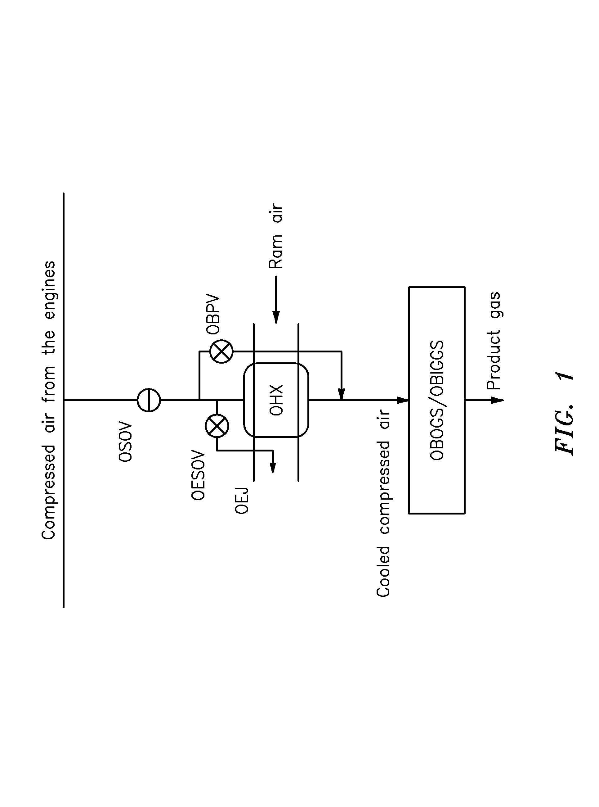
[0025]It is therefore the object of the invention to provide a system for the cooling of compressed air for the supply of an OBOGS and / or OBIGGS or of units with similar compressed air requirements having a low weight which takes up little space and is cost favorable.
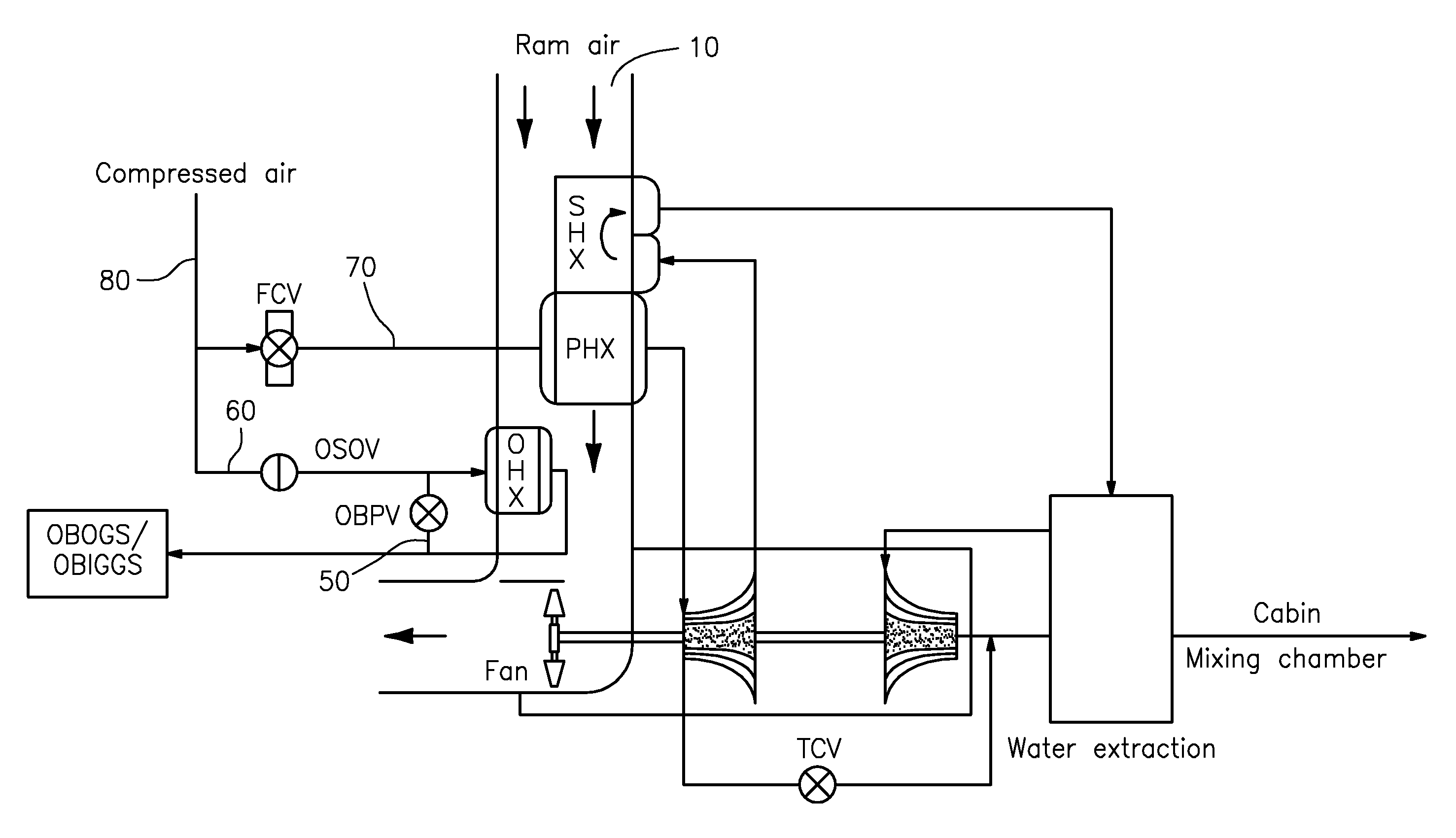
[0031]a) Weight and space savings due to the omission of the separate OBOGS / OBIGGS ram air passage and its inlets and outlets. The effect on the size of the ram air passage of the aircraft air conditioning system due to the added system heat exchanger OHX is small, since the ram air requirement for the system heat exchanger OHX is relatively small. The weight effect of the OHX remains neutral, that is it is independent of whether it is installed in a separate ram air passage or in a common ram air passage together with the heat exchangers of the air conditioning system.
[0036]b) With a parallel OHX arrangement, as will be explained with reference to FIG. 3, and with a switched off OBOGS / OBIGGS, a useless ram air throughput takes place through the system heat exchanger OHX. In particular in ground operation, the disadvantage consists of the fact that the fan conveys ram air / environmental air uselessly through the system heat exchanger OHX and this ram air does not flow through the ram air heat exchanger of the air conditioning system (air conditioning system heat exchanger). The maximum possible cooling capacity of the air conditioning system is thereby reduced.
[0037]These disadvantages can be avoided by the connection in accordance with the invention by means of a closable line between the outlet of the OHX on the compressed air side and the line system of the air conditioning system on the compressed air side in communication with the at least one air conditioning system heat exchanger or with the at least one air conditioning system heat exchanger itself. When the systems OBOGS / OBIGGS are switched off, the cooling capacity of the system heat exchanger OHX can be utilized for the air conditioning system. If the system heat exchanger OHX is also available for the air conditioning system in the case of maximum cooling, the ram air heat exchanger(s) of the air conditioning system (air conditioning system heat exchangers) can be reduced due to the additional heat transfer capacity, which is accompanied by corresponding advantages with respect to weight and construction space.
[0064]Provision can furthermore be made for the system heat exchanger OHX and the at least one air conditioning system heat exchanger to be charged through a common inlet, but by means of a separate supply, with ram air or environmental air and for a ram air inlet flap to be provided which, in its closed position, only closes the infeed of the air conditioning system heat exchanger on the ram air side, with the ram air inlet flap being closed in heating operation so that the ram air or environmental air only flows through the system heat exchanger in heating operation. It can thus be ensured that ram air or environmental air also flows through the ram air passage with a completely closed ram air passage flap.

Problems solved by technology

The failure of one of these systems or a high leakage of the cabin results in a drop in cabin pressure.
Furthermore, heavy smoke development in the cabin can occur due to different malfunctions.
This emergency oxygen system is, however, associated with various disadvantages such as weight, limited oxygen quantity, space requirements, risk of explosion and time-consuming and expensive inspection and refilling.
The OBOGS is very rarely in operation since the probability of a failure of the cabin pressurization is very low due to the integrated redundancies.
On an unfavorable composition, an explosive mixture can arise which ignites itself or due to spark formation.
Since no ram air is available in this operating state due to the lack of ram pressure, it must be actively conveyed.
Both versions are associated with disadvantages of cost and weight.

Method used


Image

  • System for the preparation of compressed air
  • System for the preparation of compressed air
  • System for the preparation of compressed air

Examples


Embodiment Construction

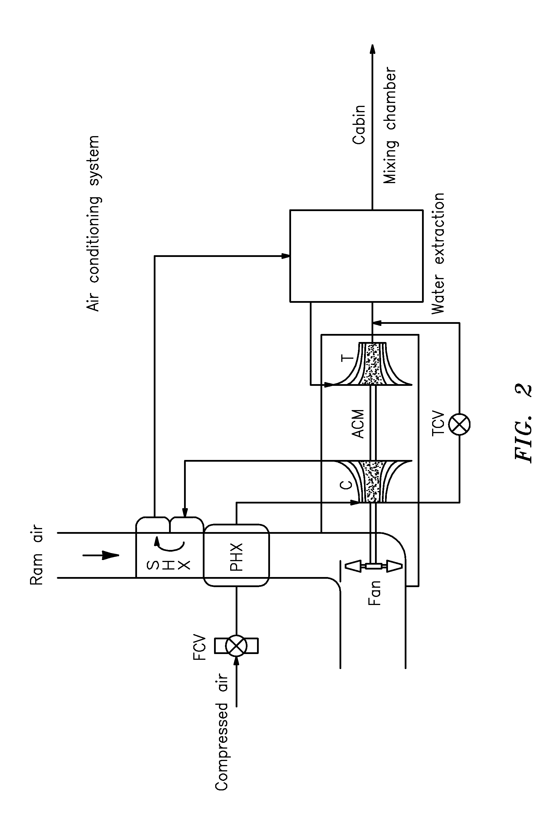
[0076]Parts which are the same or which correspond in their function are provided with the same reference symbols in the Figures.

[0077]FIG. 2 shows the typical design of an aircraft air conditioning system.

[0078]Hot pressurized air from the engines or from an auxiliary unit is supplied to the flow control valve FCV of the air conditioning system (approximately 200° C. and 3 bar). This air is pre-cooled to approximately 100° C. in the pre-heat exchanger PHX and subsequently further compressed in a compressor C. A second cooling of the compressed air in the main heat exchanger SHX to approximately 40° C. then takes place with a subsequent dehumidification in a water extraction system. The dehumidified air is then expanded in the turbine T and cooled in this process to approximately −30° C. The shaft power arising at the turbine is used to drive the compressor and a fan to convey PHX / SHX ram air or ambient air. The air flows from the turbine outlet through the water extraction system a...


PUM


Abstract

A method and a system for the preparation of compressed air having a heat exchanger (system heat exchanger) which is in communication with a pressure source on the inlet side on the compressed air side and which is in communication with a system or unit on the outlet side on the compressed air side which is to be supplied with cooled compressed air and including at least one heat exchanger (air conditioning system heat exchanger) which is in communication with a pressure source on the inlet side on the compressed air side and which is in communication with additional components of an aircraft air conditioning system on the outlet side on the compressed air side. Provision is made for the system heat exchanger and the at least one air conditioning system heat exchanger to have a common inlet for supply with ram air or environmental air and for the system heat exchanger to be connected on its outlet side on the compressed air side via a closable line to the line system on the compressed air side in communication with the at least one air conditioning system heat exchanger or to the at least one air conditioning system heat exchanger itself.

Description

BACKGROUND OF THE INVENTION[0001]The invention relates to a system for the preparation of compressed air having a heat exchanger (system heat exchanger) which is in communication with a pressure source on the inlet side on the compressed air side and which is in communication with a system or unit on the outlet side on the compressed air side which is to be supplied with cooled compressed air and comprising at least one heat exchanger (air conditioning system heat exchanger) which is in communication with a pressure source on the inlet side on the compressed air side and which is in communication with further components of an aircraft air conditioning system on the outlet side on the compressed air side.[0002]In a preferred aspect, the invention relates to an architecture for the preparation of compressed air which is required for the operation (supply) of oxygen and nitrogen generating units in aircraft.[0003]With passenger aircraft, it is necessary to control the temperature of th...

Claims


Application Information

Patent Timeline
IPC IPC(8): F25D9/00B64D33/02B64D13/02B64D13/08B64D37/32
CPCB64D37/32B64D2013/0677Y02T50/44Y02T50/40
Inventor BRUTSCHER, NORBERTHAAS, JOACHIM
Owner LIEBHERR AEROSPACE LINDENBERG
Learn More