
CO2 separation from low-temperature flue gases

Inactive Publication Date: 2010-11-30
THE UNITED STATES AS REPRESENTED BY THE DEPARTMENT OF ENERGY
View PDF9 Cites 31 Cited by
  • Summary
  • Abstract
  • Description
  • Claims
  • Application Information

AI Technical Summary

Benefits of technology

[0031]Another object of the present invention is to provide an improved method for extracting carbon dioxide from a fluid stream. A feature of the invention is using a scrubbing solution (i.e., phase-separating moiety) with a basic moiety, whereby the phase-separating moiety provides carbonate ion in the solution, and regenerates the basic moiety in situ. An advantage of these features is that overall carbon dioxide absorption capacity of the scrubbing solution is increased.
[0037]Yet another object of the present invention is to provide a method which provides a phase-separating moiety with a lower regeneration heat requirement. A feature of this invention is that the regeneration heat requirements of alkali metal hydrogen carbonates (bicarbonates) are lower than that of commonly used aqueous solutions of MEA. An advantage of this feature is lower energy requirements to release CO2 gas.

Problems solved by technology

Post-combustion capture of CO2 poses a significant engineering challenge because (1) the low pressure and dilute concentration of the carbon dioxide dictate a high actual volume of gas to be treated; (2) trace impurities in the flue gas tend to reduce the effectiveness of CO2 absorbing processes; and (3) compressing captured CO2 from atmospheric pressure to pipeline pressure (1,200-2,000 pounds per square inch (psi)) represents a large parasitic energy load to the overall power generation process.
No significant chemical degradation is observed, but physical attrition can be significant.
Loss of K2CO3 from composite beads results in decreased CO2 bearing capacity of the beads.
The use of MEA solutions is energy-intensive, corrosive and follows the reaction equation infra
The regeneration also causes some degradation of the amine.
A limitation of this method is the relatively low rate of reaction resulting from the limited solubility of CO2 in these mixtures.
The Solvay process was not designed for CO2 sequestration and is not practical for use in the sequestration of CO2 from fossil fuel power plants.
None of the aforementioned patents or papers disclose a method to regenerate CO2-loaded aqueous amine solutions (MEA or similar amines) through reaction with a phase-separating reagent such as dissolved alkali metal carbonates, alkaline earth metal oxides, or alkaline earth metal hydroxides.
Also, none of the aforementioned patents or papers disclose a method to capture carbon dioxide via phase separation of dissolved CO2 as a crystalline solid precipitate.
Furthermore, none of the aforementioned patents or papers disclose a method to accomplish rapid crystalline solid precipitate alkali metal bicarbonate formation through catalysis by MEA or similar amines.
Also, none of the aforementioned patents or papers disclose a method to accomplish rapid alkaline earth metal oxide or alkaline earth metal hydroxide carbonation through catalysis by MEA or similar amines.
In addition, none of the aforementioned patents or papers disclose a method to use bases and base anhydrides present in industrial wastes as capture agents for CO2 by suspending the wastes in aqueous solutions of MEA or similar inhibited amines.

Method used


Image

  • CO2 separation from low-temperature flue gases
  • CO2 separation from low-temperature flue gases
  • CO2 separation from low-temperature flue gases

Examples


example 1

Closed Loop CO2 Separation Via Phase-Separation Reagent with Thermal Regeneration and Amine Absorption Reagent with Chemical Regeneration

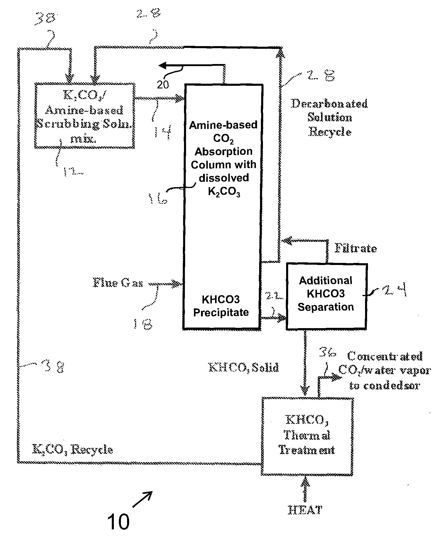
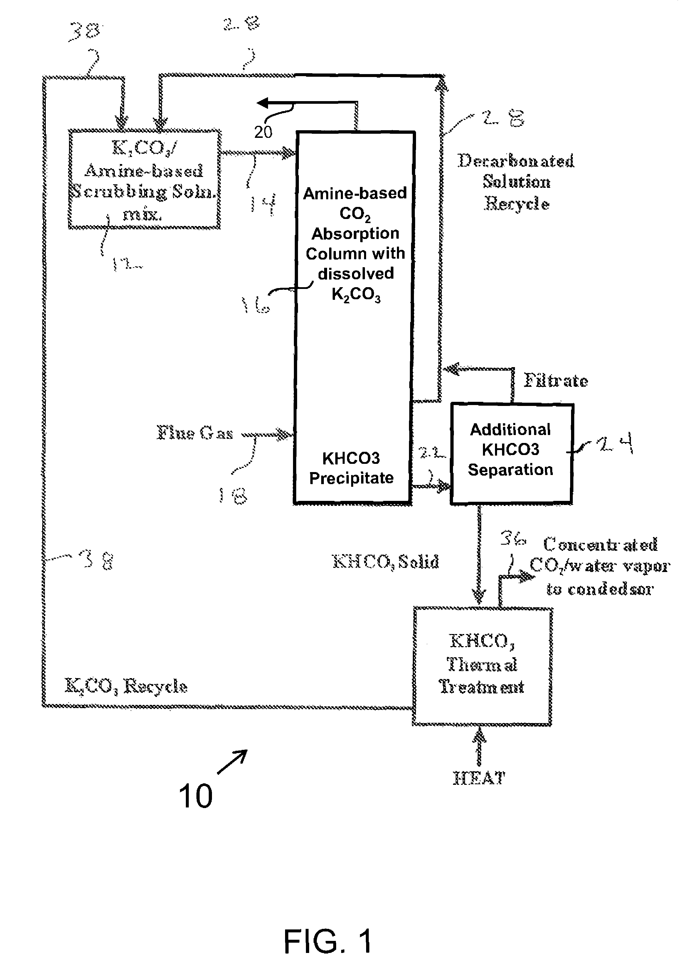
[0117]The inventors have found the dissolution of the phase-separating moiety in the first method to enable the ready mixing of carbon dioxide and the phase-separating moiety in a way that is independent of the surface area of the carbon dioxide-capturing moiety. This greatly increases the efficacy of the invention. In the first method, the phase-separating moiety is dissolved in water to which a basic scrubbing moiety is also added. The basic scrubbing moiety is conserved throughout the process of absorption and chemical regeneration.

[0118]Absorption and regeneration temperatures are given in Table 1 supra for compounds of potassium and sodium.

[0119]Heat energy for the regeneration of the phase-separating moiety can be taken from the exothermic scrubbing reactions as noted in Examples 1 and 2 infra and from low-grade steam from the power plant its...

example 2

Once-Through Carbonation of Waste Materials

[0125]Reactions similar to those with NaHCO3 and KHCO3 were carried out employing a 20 percent (mass percent) solution of MEA in water and reagent-grade calcium hydroxide (Ca(OH)2) (solubility of 0.185 grams (g) / 100 cubic centimeters (cm3) of water at 0° C.). Separately, reactions were carried out with a 20 percent (mass percent) solution of MEA in water and CaO / Ca(OH)2-bearing waste materials such as waste cement or fly ash. (The solubility of calcium oxide is 0.131 g / 100 cm3; however, CaO reacts with water and is converted to Ca(OH)2.) The particle sizes ranged between 230 and 200 mesh, 63 and 75 micrometers (μm) respectively.

[0126]In a manner similar to that of Example 1 supra, carbon dioxide was loaded for 10 min at a rate of approximately 3 L / min into approximately 80 mL of 20 percent aqueous MEA (mass percent) with the occurrence of mild heat generation. The solids were partially suspended as a result of sparger turbulence, but active...


PUM

PropertyMeasurementUnit
Fractionaaaaaaaaaa
Particle sizeaaaaaaaaaa

Abstract

Two methods are provide for the separation of carbon dioxide from the flue gases. The first method utilizes a phase-separating moiety dissolved in an aqueous solution of a basic moiety to capture carbon dioxide. The second method utilizes a phase-separating moiety as a suspended solid in an aqueous solution of a basic moiety to capture carbon dioxide. The first method takes advantage of the surface-independent nature of the CO2 absorption reactions in a homogeneous aqueous system. The second method also provides permanent sequestration of the carbon dioxide. Both methods incorporate the kinetic rate enhancements of amine-based scrubbing while eliminating the need to heat the entire amine solution (80% water) in order to regenerate and release CO2. Both methods also take advantage of the low-regeneration temperatures of CO2-bearing mineral systems such as Na2CO3 / NaHCO3 and K2CO3 / KHCO3.

Description

CONTRACTUAL ORIGIN OF THE INVENTION[0001]The United States Government has rights in this invention pursuant to the employer-employee relationship of the Government to the inventors as U.S. Department of Energy employees at the National Energy Technology Laboratory.BACKGROUND OF THE INVENTION[0002]1. Field of the Invention[0003]This invention relates to an improved method of separating carbon dioxide from fluids, and more specifically, this invention relates to an improved method of separating carbon dioxide from flue gases that utilizes amine-based scrubbing and low regeneration temperatures of CO2 bearing mineral systems to permanently sequester carbon dioxide.[0004]2. Background of the Invention[0005]Increased global warming due to the presence and production of greenhouse gases such as carbon dioxide (CO2), makes the capture and permanent sequestration of carbon dioxide by economical means imperative.[0006]Carbon dioxide capture is the separation of CO2 from emissions sources or ...

Claims


Application Information

Patent Timeline
IPC IPC(8): B01D53/14B01D53/62
CPCB01D53/1475B01D53/62B01D53/78B01D53/80B01D2251/302B01D2251/304B01D2251/306B01D2251/402B01D2251/404B01D2251/80Y02C10/04Y02C10/06Y02A50/20Y02C20/40
Inventor DILMORE, ROBERTALLEN, DOUGLASSOONG, YEEHEDGES, SHEILA
Owner THE UNITED STATES AS REPRESENTED BY THE DEPARTMENT OF ENERGY
Learn More