Tube pump, liquid ejecting apparatus, and method of driving tube pump

a tube pump and liquid ejector technology, applied in the direction of machines/engines, liquid fuel engines, positive displacement liquid engines, etc., can solve the problems of deterioration of friction between the roller and the tube, failure of printing, and irregular magnitude of friction, etc., to achieve the effect of suppressing irregular movemen

Inactive Publication Date: 2010-11-30
SEIKO EPSON CORP
View PDF6 Cites 2 Cited by
  • Summary
  • Abstract
  • Description
  • Claims
  • Application Information

AI Technical Summary

Benefits of technology

[0013]Aspects of the invention comprise a tube pump, a liquid ejecting apparatus, and a method of driving the tube pump capable which are capable of suppressing any irregular movement of a pressing member between a pump non-operating and a pump operating position.
[0017]In these configurations, the pressing member rotatably moves from the pump non-operating position to the pump operating position during the pump operating process, causing the pinion member to engage with the rack member. Accordingly, the movement speed of the pressing member does not vary in accordance with the magnitude of the friction between the pressing member and the tube, unlike the known examples. Therefore, it is possible to suppress any irregular movement of the pressing member as it moves from the pump non-operating position to the pump operating position.

Problems solved by technology

For any of these reasons, the nozzles may become clogged, and cause a printing failure.
One problem with this configuration, however, is that when the roller moves from the pump non-operating position to the pump operating position as the pump foil is rotated toward the pump operating position, due to the difference in friction between the roller and tube and the friction between the roller shaft edge of the roller support groove.
Unfortunately, however, the magnitude of the friction is often irregular due to variations in the environment (such as a temperature or humidity), or the reaction force varying because of irregularity in the tube shape.
Additionally, since the tube pump is mounted in the printer, ink may leak into the housing, lubricating the area between the roller and the tube, causing the friction between the roller and the tube to deteriorate.
Without a substantial difference in these speeds, the roller shaft does not properly move in the roller support groove.
As such, the roller may not adequately move from the pump non-operating position to the pump operating position, meaning that the tube pump may not function as a pump.
Thus, it has difficult to successfully design the tube pump so that the difference in friction between roller and the tube and the friction caused by the roller shaft the roller support groove is constant and reliable.

Method used


Image

  • Tube pump, liquid ejecting apparatus, and method of driving tube pump
  • Tube pump, liquid ejecting apparatus, and method of driving tube pump
  • Tube pump, liquid ejecting apparatus, and method of driving tube pump

Examples


Embodiment Construction

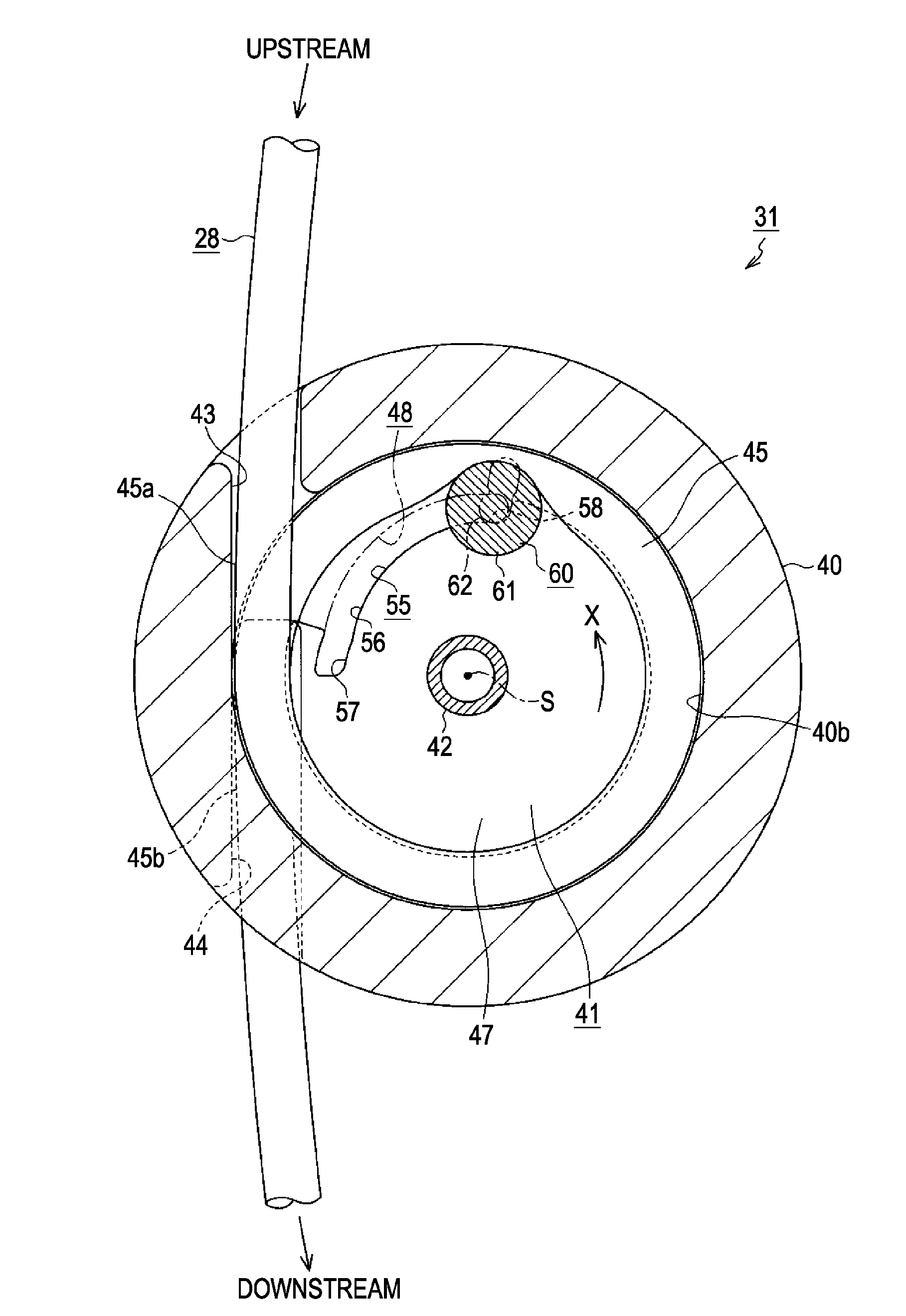
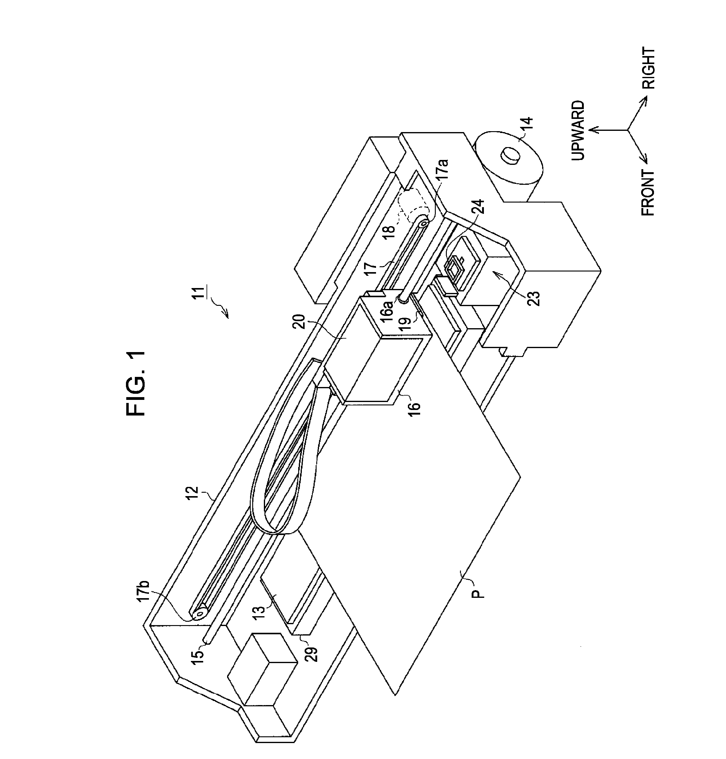
[0031]Hereinafter, a tube pump, a liquid ejecting apparatus, and a method of driving the tube pump according to an embodiment of the invention will be described with reference to FIGS. 1 to 11. In addition, in the following description, the “front,”“rear,”“upward,”“downward,”“left,” and “right” directions are as shown in FIG. 1.

[0032]FIG. 1 shows an ink jet printer 11, which is an example of a liquid ejecting apparatus that may be used in association with the invention. The ink jet printer 11 includes a frame 12 with substantially a rectangular box shape. A platen 13 is arranged so as to extend along the in the right and left direction in the lower portion of the frame 12. A paper sheet P is configured to be fed from a rear side of the platen 13 by a sheet feeding mechanism (not shown) when a paper feeding motor 14 provided in the lower rear surface of the frame 12 is driven.

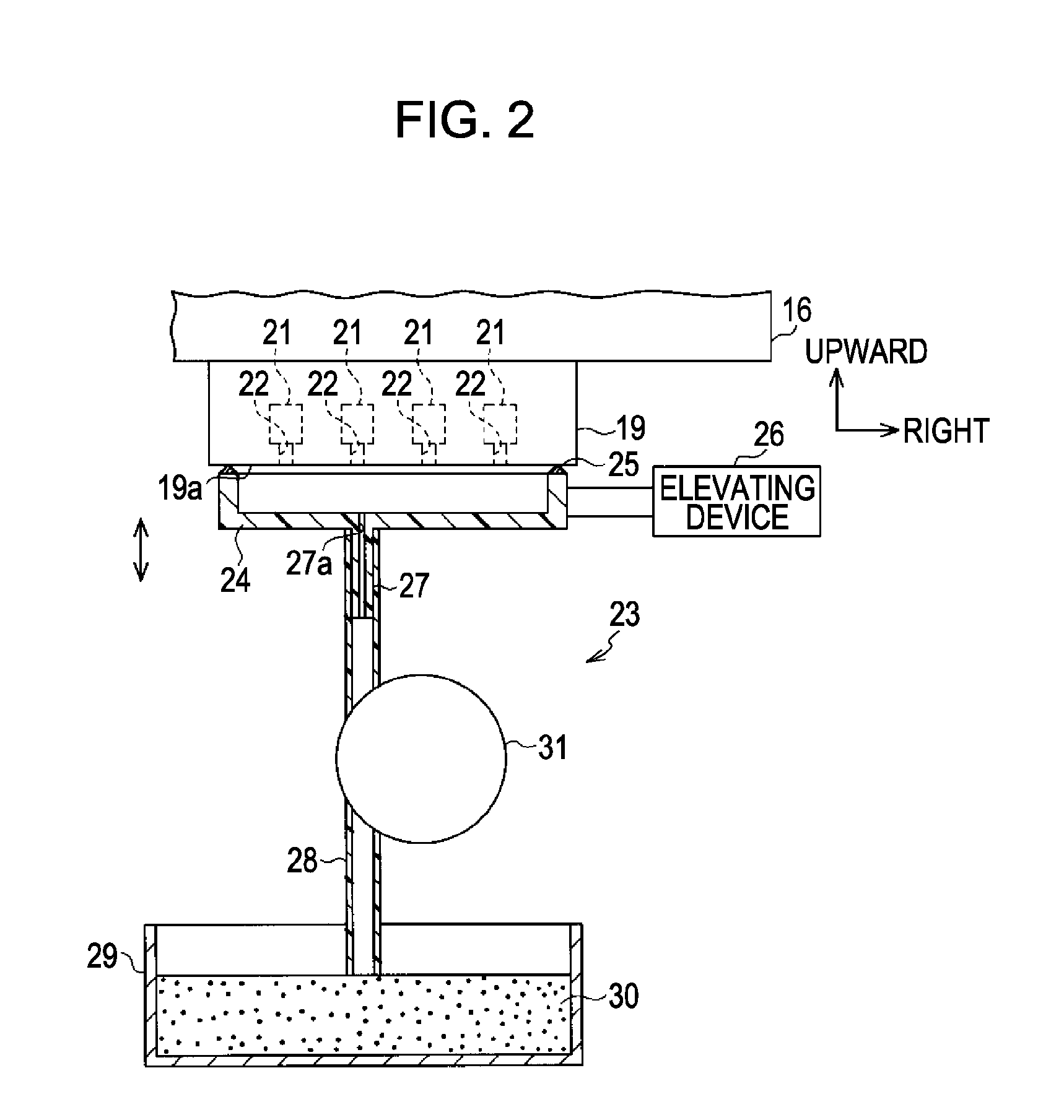
[0033]A guide shaft 15 is arranged along the upper portion of the platen 13. A carriage 16 is supported on th...


PUM


Abstract

A tube pump comprising a flexible tube, a pressing member capable of generating a negative pressure in the tube by sequentially pressing the tube from as the pressing member moves from an upstream portion of the tube to a downstream portion of the tube during a pump operating process, a rotating member which includes a cam surface which the pressing member comes in sliding contact with when the pressing member moves between a pump operating position where a negative pressure is generated in the upstream portion of the tube and a pump non-operating position where the negative pressure is not generated, and a rack member corresponding to the cam surface which includes a plurality of teeth, wherein the pressing member is provided with a pinion member capable of engaging with the rack member when the pressing member rotatably moves between the pump non-operating position and the pump operating position.

Description

BACKGROUND OF THE INVENTION[0001]The entire disclosure of Japanese Patent Application No. 2007-076900, filed Mar. 23, 2007 is expressly incorporated herein by reference.[0002]1. Technical Field[0003]The present invention relates to a tube pump More specifically, the present invention relates to a method of driving a tube pump and a liquid ejecting apparatus having the tube pump, which is capable of suppressing any irregular movements of the tube pump as it is switched from a non-operating position to an operating position.[0004]2. Related Art[0005]An ink jet printer is a liquid ejecting apparatus capable of ejecting a liquid onto a target from a liquid ejecting head. During a standard printing process, ink solvent vaporizes from series of openings in the nozzles formed on a nozzle formation surface of a printing or liquid ejecting head. As the solvent vaporizes, the ink solidifies, attracts dust, mixes with air to create bubbles, or the like. For any of these reasons, the nozzles ma...

Claims


Application Information

Patent Timeline
Patent Type & Authority Patents(United States)
IPC IPC(8): B41J2/165
CPCB41J2/16532B41J2/17596F04B43/1238
Inventor WATANABE, EIICHIRO
Owner SEIKO EPSON CORP
Why Eureka
Try Eureka