
Near field lens

a near field lens and lens technology, applied in the field of lighting systems, can solve the problems of increasing the overall cost of the vehicle lighting system, single light-emitting diodes (leds) do not provide enough light intensity, etc., and achieve the effect of brighter light intensity

Active Publication Date: 2010-11-23
VARROC LIGHTING SYST SRO
View PDF16 Cites 31 Cited by
  • Summary
  • Abstract
  • Description
  • Claims
  • Application Information

AI Technical Summary

Benefits of technology

The solution provides brighter light intensity with reduced system size and complexity, meeting automotive industry requirements effectively.

Problems solved by technology

In automotive vehicle lighting applications, a single light-emitting diode (LED) does not provide enough light intensity to meet the light intensity requirements of the application.
However, multiple LED and lens assemblies increase the size and complexity of the packaging of the vehicle lighting system, increasing the overall cost of the vehicle lighting system.

Method used


Image

  • Near field lens
  • Near field lens
  • Near field lens

Examples


Embodiment Construction

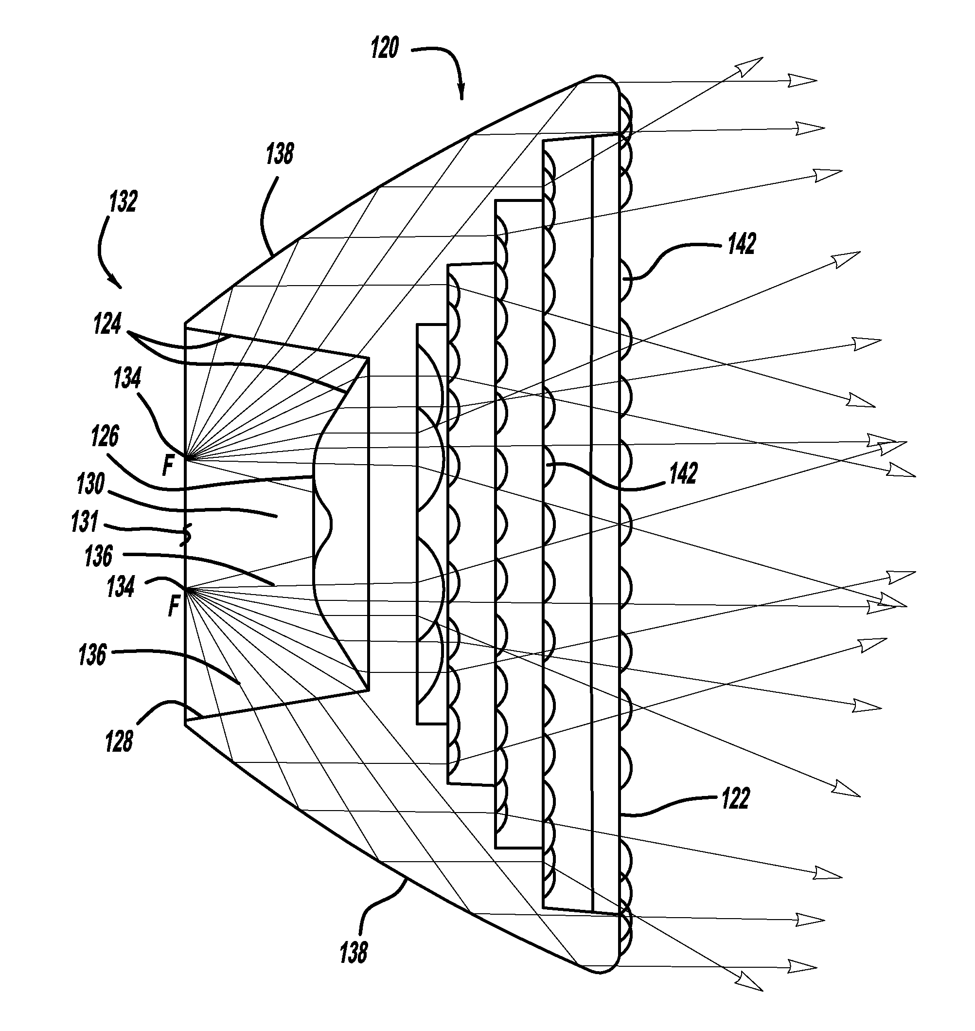
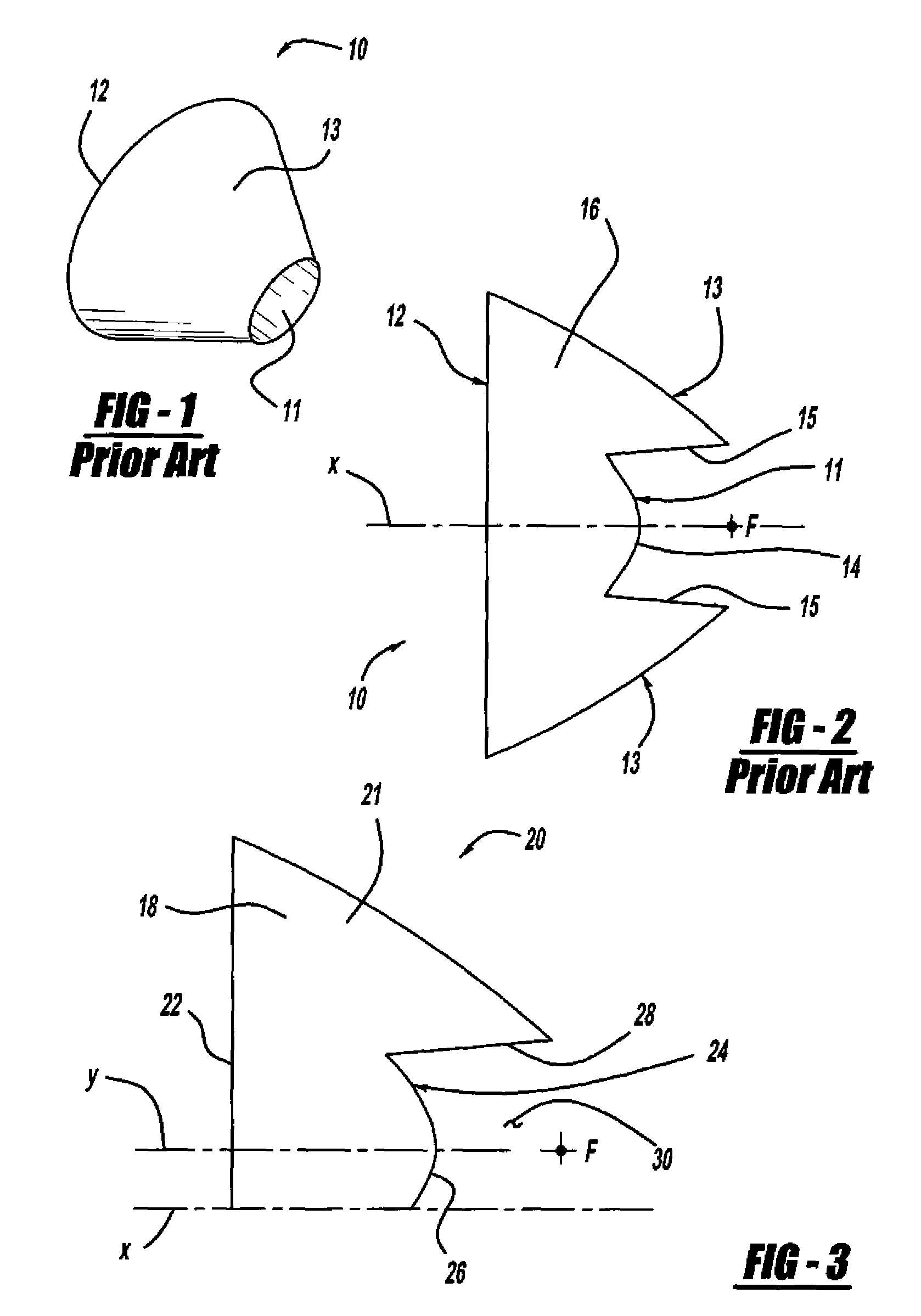
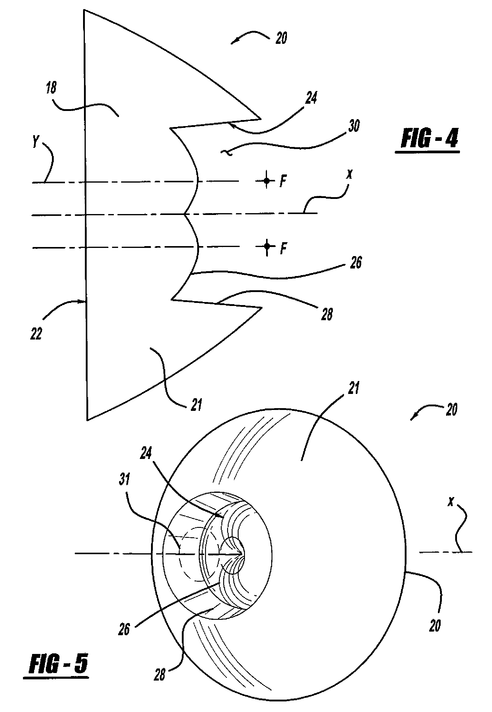
[0018]Referring now to FIGS. 3-5, the present invention generally provides a near field lens 20 for use with multiple light sources, preferably LEDs. Because multiple LEDs may be used with a single near field lens 20 embodying the principles of the present invention, the size and complexity of a lighting system may be reduced.

[0019]Referring to the top half 18 cross section of the lens 20 seen in FIG. 3, the lens 20 is a surface of revolution about an axis of revolution X and includes a main body 21. The main body 21 includes a light-emitting face 22 disposed opposite a light-collecting face 24. The light-collecting face 24 further has an axial surface 26 surrounded by a radial surface 28, wherein the surfaces 26, 28 define a pocket 30 in the lens 20; however, it is contemplated that the light-collecting face 24 could have other configurations without falling beyond the spirit and scope of the present invention. The axis of revolution X extends through the light-emitting face 22 and...


PUM


Abstract

A lens has a main body for use with at least one light source. The main body has a light-emitting face, a light-collecting face disposed opposite the light-emitting face, and a plurality of focal points, the latter of which form a focal ring. A central axis extends through the light-collecting face and the light-emitting face. The main body is substantially radially symmetrical about the central axis and the focal ring extends around the central axis of the main body of the lens.

Description

FIELD OF THE INVENTION[0001]The present invention generally relates to lighting systems. More particularly, the present invention relates to lighting systems that employ lenses to collect light from a light source and direct the light within the lighting system.DESCRIPTION OF RELATED ART[0002]In automotive vehicle lighting applications, a single light-emitting diode (LED) does not provide enough light intensity to meet the light intensity requirements of the application. Therefore, multiple LEDs are used. A plurality of low-powered LEDs, ten or more for example, each with its own dedicated reflector or lens optics, are used in many automotive lighting applications. Each LED typically has its own near field lens (NFL) to provide efficient light collection and distribution within the vehicle lighting system.[0003]In order for the NFL to function properly, each LED must be placed at the focal point of the NFL. NFLs typically have focal points located along a single center axis, and the...

Claims


Application Information

Patent Timeline
Patent Type & Authority Patents(United States)
IPC IPC(8): F21V5/00G02B13/20G02B3/10
CPCF21S48/1154F21S48/1159F21S48/1329F21S48/215G02B19/0061F21V5/04F21V7/0091G02B19/0028F21S48/236F21Y2101/02F21Y2115/10F21S41/322F21S43/14F21S43/315
Inventor CHINNIAH, JEYACHANDRABOSESAYERS, EDWIN MITCHELLEICHELBERGER, CHRISTOPHER L.
Owner VARROC LIGHTING SYST SRO
Learn More