
Methods and systems for intentionally isolating distributed power generation sources

a power generation source and distributed technology, applied in the field of intentionally isolating distributed power generation sources, can solve the problems of small grids generally not having much load, dg sources tend not to follow loads well, and current dg systems have various limitations

Active Publication Date: 2010-11-16
BEACON POWER LLC
View PDF12 Cites 85 Cited by
  • Summary
  • Abstract
  • Description
  • Claims
  • Application Information

AI Technical Summary

Benefits of technology

The solution provides stable frequency and voltage control, load-following capabilities, and standardizes communication protocols, enabling mini-grids to operate independently and reducing the burden on utility grids while improving communication between utilities and DG systems.

Problems solved by technology

However, current DG systems have various limitations, for example, small grids generally do not have much load or generation averaging, and need more voltage and frequency stabilization, on the order of 10-20%, as compared to most utility grids which require 1-2% adjustment for voltage and frequency stabilization.
Also, DG sources tend not to follow loads well.
Other technical limitations include the lack of a single standard for communicating with DG systems, the need for back-up, black start, and overloads, and conflicts between anti-islanding schemes.
Interconnection issues affect both DG users and utilities.
Moreover, control standards for hybrid systems can be difficult for the DG user to follow.
On the other hand, utilities receive a high demand for VARs, which are generated at the expense of real power sales.
Although DG users require a connection to the grid, utility operators see DG as a burden.
Without such a continuous connection, the mini-grid can suffer from power quality and reliability problems.
These problems revolve around two major system parameters: frequency stability and voltage regulation.
In conventional mini-grid arrangements, there is a hazard to load equipment which can be damaged by unstable grid voltage or frequency whenever the mini-grid is disconnected from the utility grid.
In some cases, the mini-grid remains connected to the utility grid so that electric power is supplied from the mini-grid to the utility grid, which can result in quality problems for the utility service provider because the power supplied to the utility grid may not satisfy voltage and frequency requirements.
When the mini-grid operates in an islanding condition, such that no electric energy flows from the utility grid to the mini-grid, the DG sources of the mini-grid may not supply sufficient real power or reactive power to satisfy the requirements of the load-bearing equipment.
Even if the real power generated temporarily matches the loads, there may be problems associated with frequency regulation and voltage regulation, as discussed above.
Moreover, the selection or combination of DG sources linked to the mini-grid may result in load-following or power quality problems.
For example, fuel cells may trip offline due to large transient cyclic loads, while synchronous generators tend to simply shut down when the mini-grid is isolated or disconnected from the utility grid.
Unfortunately, the lack of standardization in communication protocols and physical connections for DER systems often makes it impractical for utilities and area operators to gain access to these mini-grids / DER systems.
The situations is further complicated by sites with multiple DER systems and mini-grids requiring separate communication channels.
Presently available devices and techniques do not provide substantial frequency stability and load-following capabilities to permit substantially continuous operation of a mini-grid when disconnected from the utility grid.

Method used


Image

  • Methods and systems for intentionally isolating distributed power generation sources
  • Methods and systems for intentionally isolating distributed power generation sources
  • Methods and systems for intentionally isolating distributed power generation sources

Examples


Embodiment Construction

)

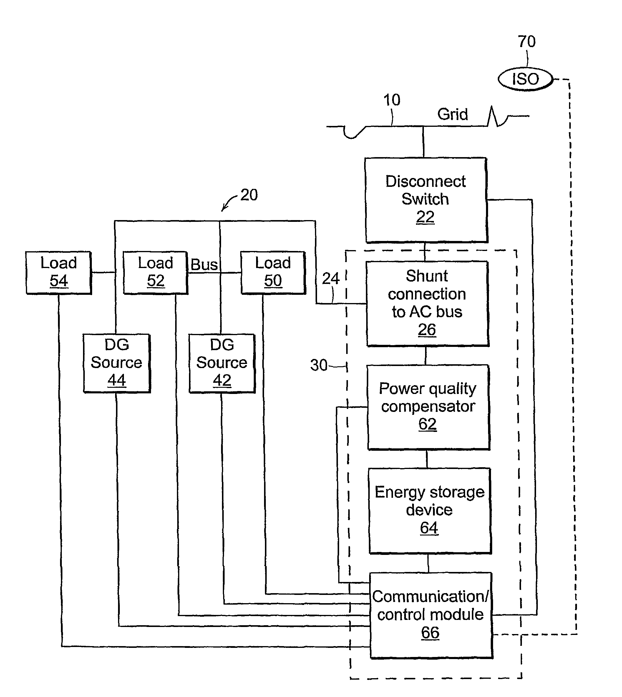
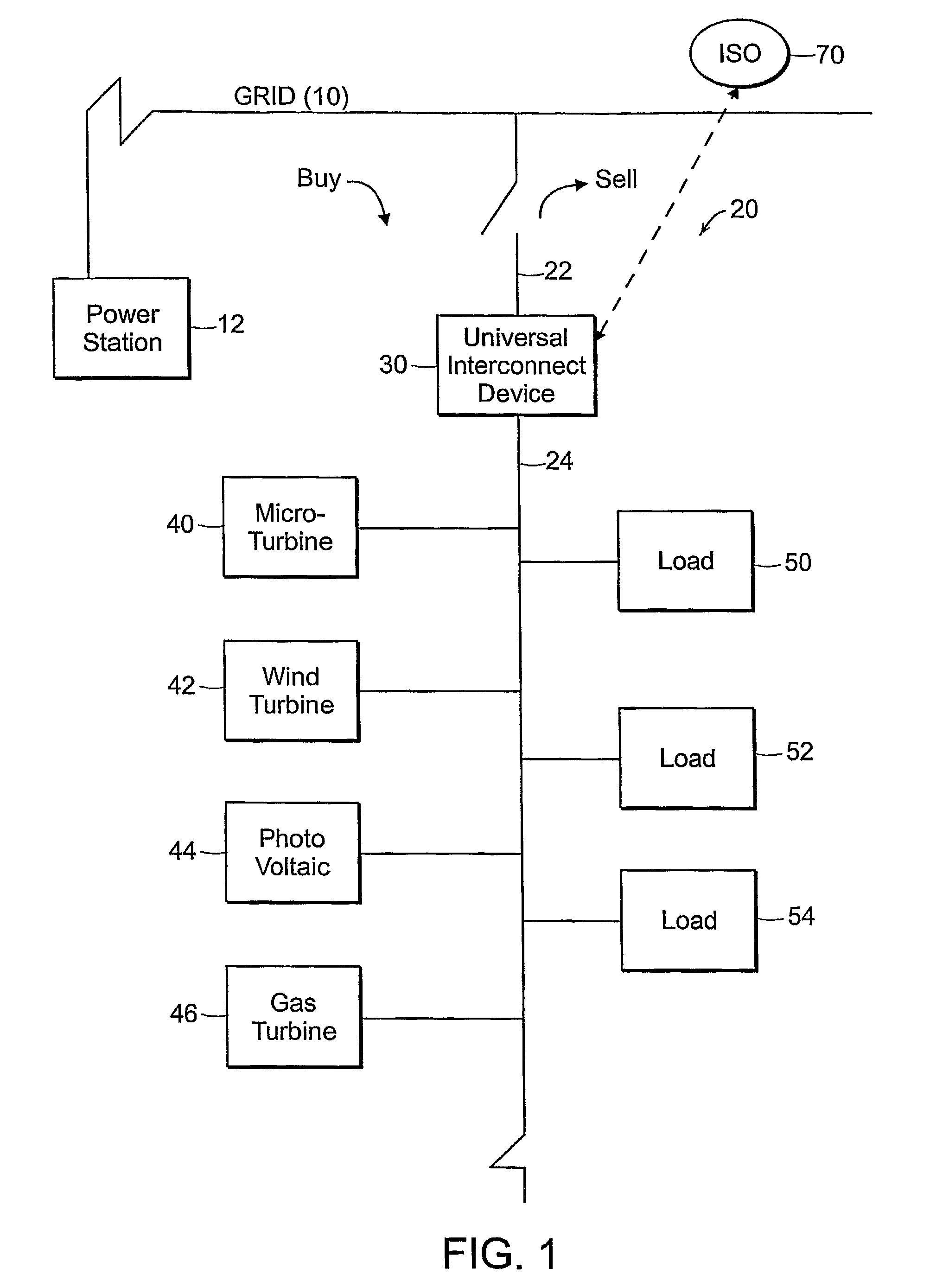
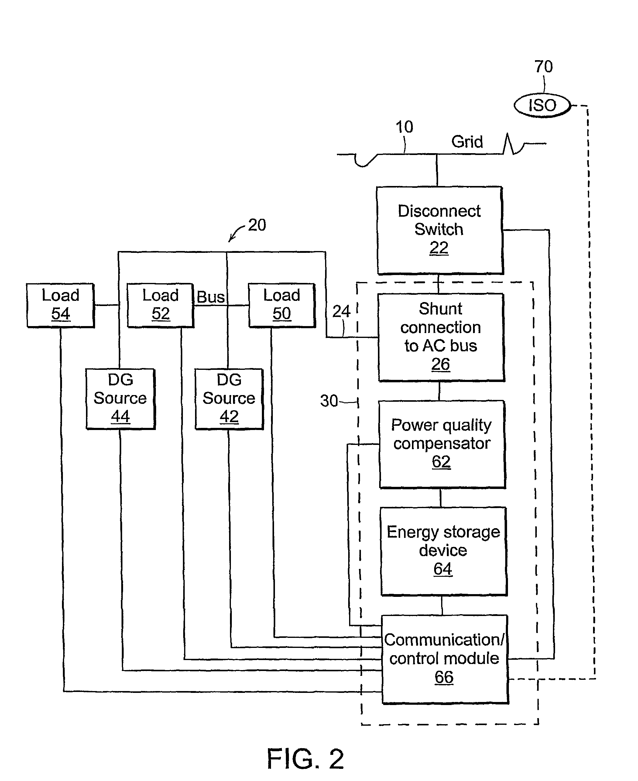
[0036]Referring now to the various figures of the drawing wherein like reference characters refer to like parts, there is shown in FIG. 1 a block diagram of an exemplary system for connecting one or more distributed generation (DG) sources and one or more loads to form a mini-grid. The mini-grid preferably is configured and arranged to be connected to a utility grid, where the mini-grid can be a distributed energy resources (DER) system made up of one or more DG sources and one or more loads. Suitable DG sources include but are not limited to: turbine generators, internal combustion engines / generators, micro-turbines, gas turbines, photovoltaics / solar panels, wind turbines, fuel cells, batteries, capacitor-type storage systems, and flywheel energy storage systems. Any number or combination of these sources can be provided, depending upon the application or the particular mini-grid.

[0037]As shown in FIG. 1, the utility grid 10 can be operated by a utility service provider or area op...


PUM


Abstract

A method and system for operating a mini-grid including one or more power generation sources and one or more loads independently from a utility grid is provided, where the mini-grid is disconnected from the utility grid in response to a power disruption over the utility grid. A universal interconnect device forms a connection between the mini-grid and the utility grid. In the disconnected state, the mini-grid operates independently from the utility grid, such that the power generation sources of the mini-grid supply the loads. Frequency and voltage regulation are provided by the universal interconnect device through a monitoring function performed by a controller in conjunction with at least an energy storage device, which can absorb or generate power as needed.

Description

CROSS-REFERENCE TO RELATED APPLICATION[0001]This application claims the benefit of U.S. Provisional Application Ser. No. 60 / 657,842 filed on Mar. 1, 2005, the teachings of which are incorporated herein by reference.FIELD OF INVENTION[0002]The subject invention relates to methods and systems for intentionally isolating one or more distributed power generation sources connected to a mini-grid, and more particularly relates to methods and systems for disconnecting a mini-grid including one or more distributed generation (DG) sources from a utility grid and operating the mini-grid independently.BACKGROUND OF THE INVENTION[0003]Distributed generation (DG) is the use of power generation technologies located close to one or more loads being served. Distributed energy resources (DER) is another term describing the use of one or more DG sources and / or other components that are interconnected with the utility grid. Such interconnection involves assembling the various components in such a mann...

Claims


Application Information

Patent Timeline
Patent Type & Authority Patents(United States)
IPC IPC(8): H02J3/01
CPCH02J3/04H02J3/28H02J3/38
Inventor CAPP, F. WILLIAMLAZAREWICZ, MATTHEW L.ROJAS, HERNAN ALEX
Owner BEACON POWER LLC
Learn More