Bone densitometer and a method thereof

a bone densitometer and bone technology, applied in the field of bone densitometers, can solve the problems of reducing the accuracy and precision of measurement, generating sos measurement errors, and insufficient measurement accuracy of parameters, so as to reduce the error in the measurement of several diagnostic parameters, prevent cross infection among several patients, and be easily replaced and disposable

Inactive Publication Date: 2010-11-16
LARSEN & TOUBRO
View PDF6 Cites 1 Cited by
  • Summary
  • Abstract
  • Description
  • Claims
  • Application Information

AI Technical Summary

Benefits of technology

[0011]An object of the invention is to improve the accuracy and the sensitivity of the measurement of bone characteristics by using a multi variable approach and by utilizing more than three (and ideally four) parameters to assess the bone status completely and to improve the accuracy of diagnosis.
[0012]An object of the invention is to improve the accuracy in calculating the velocity of the sound through the heel by calculating the thickness and instead of assuming a fixed thickness for the soft tissue surrounding the calcaneous.
[0013]An object of the invention is to improve the accuracy of calculating the velocity of sound through the heel by computing the coupling pad thickness (amount of squish) on both sides of the heel instead of assuming a fixed amount of squish for the coupling pads during SOS measurement process.
[0015]An object of the invention is to use an advanced programmable logic like field programmable gate array (FPGA) along with digital signal processor (DSP) instead of using conventional analog, digital and micro processor based system to control several timing signals accurately to reduce the error in the measurement of several diagnostic parameters.
[0016]An object of the invention is to use the easily replaceable and disposable coupling pads (gel pads) so that the cross infection among several patients is prevented by using easily replaceable and disposable coupling pads. The gel pads are also bacteriostatic.

Problems solved by technology

In some conventional bone assessment techniques such as, for example, a QUS technique, for measuring the physical properties of the bone, there are several sources of error and factors that reduce the accuracy and the precision of the measurement result.
For example, the assumption of a soft tissue of fixed thickness around the heel during the estimation of ultrasound velocity generates an error in SOS measurement.
Since both the BUA and SOS values are used independently to calculate the bone mineral density (BMD), the accuracy of the measurement of the parameters is not sufficiently high.
An error is also generated in speed of sound (SOS) measurement during the usage of dry coupling pads due to the variation in the quantity of squish in the coupling pad on contact with the heel of subject depending on the shape of the heel of the patient.
Moreover, an error in the measurement of SOS Parameters is generated due to the variation in the timing signals like activating time, switching time of ultrasound transducers and time of detection of received ultrasound signal at receiver above a specified threshold due to the limitation of hardware and processing speed.
Even a small variation caused due to abovernentioned factors induces unacceptable variation in various diagnostic parameters.
All the ultrasound based measurement devices using dry coupling pads (gel pads) do not provide sufficient safety from cross infection as the same set of coupling pads is used for several patients.

Method used


Image

  • Bone densitometer and a method thereof
  • Bone densitometer and a method thereof
  • Bone densitometer and a method thereof

Examples


Embodiment Construction

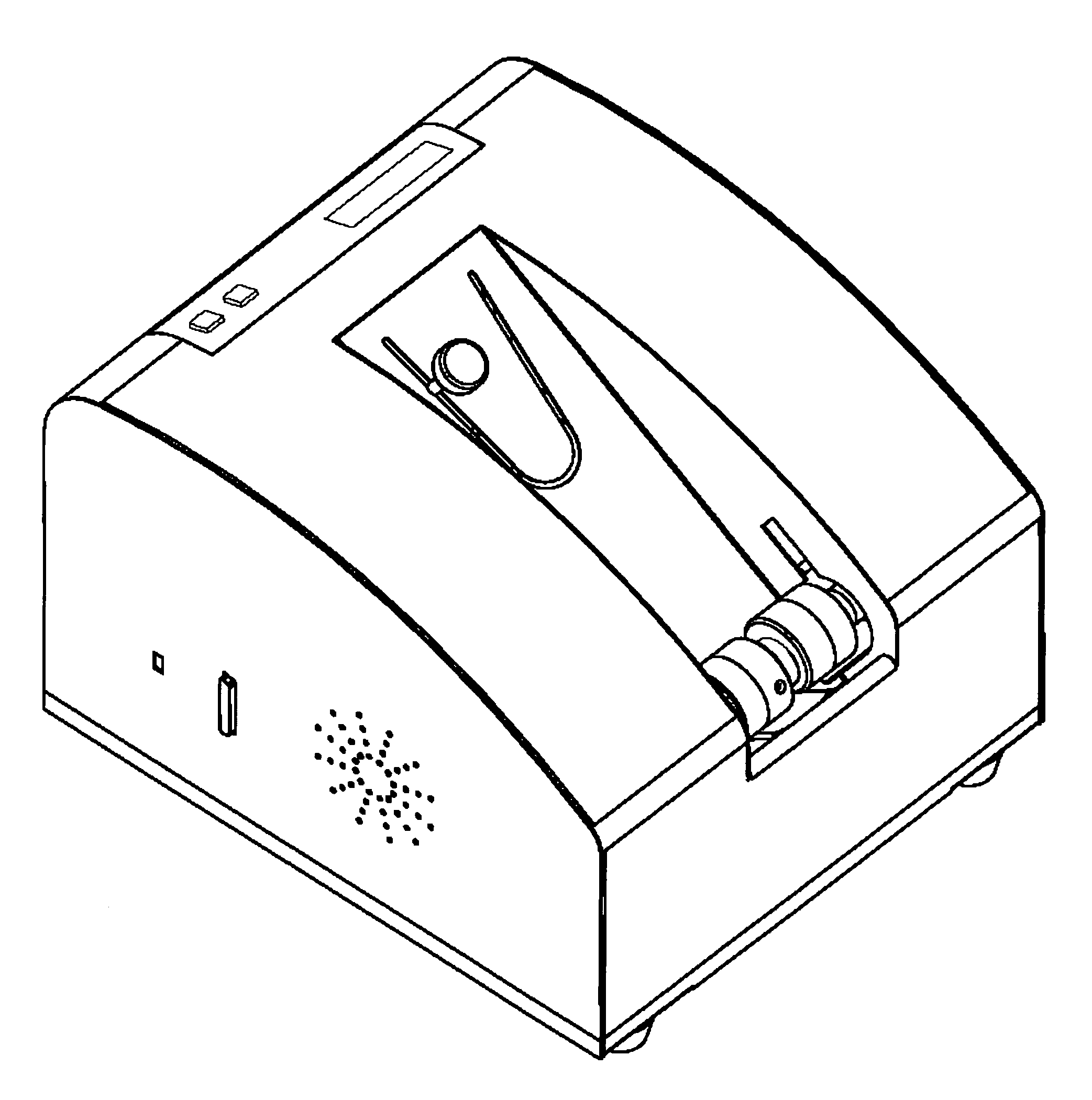
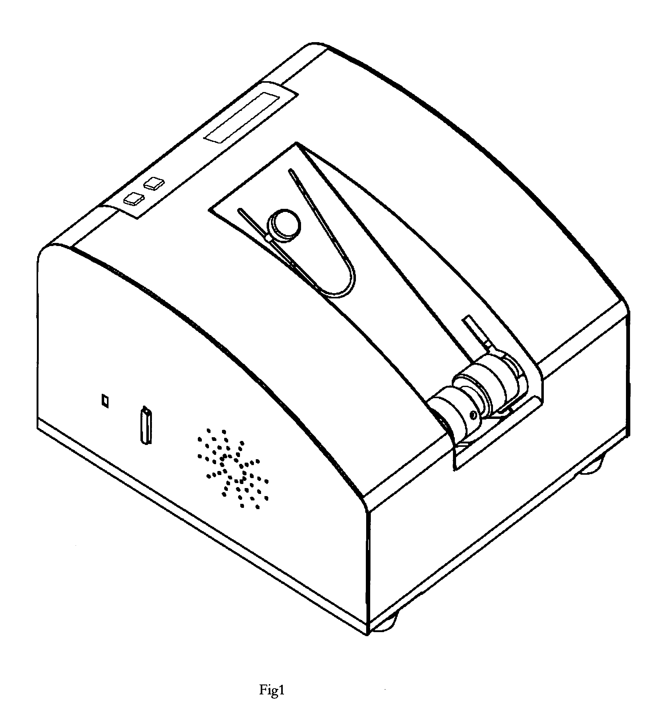
[0026]FIG. 1 shows an embodiment of a bone condition assessment device according to this invention. Accordingly, the device has a movable assembly provided at both ends with an ultrasonic transducer so that the transducers at both ends are moved towards or away from each other. The transducer acts as a transmitter or a receiver or a transceiver. The transducers may or may not be in direct contact with the body part such as heel or any other bone under test of a subject or human being. The transducers are removable and may be used as a single entity to measure or analyze the bone condition without requiring another transducer. Thus, it should be noted that the measurement site is not restricted to heel and the measurement may be carried out in any location. A foot receptacle is provided to receive a body part such as heel.

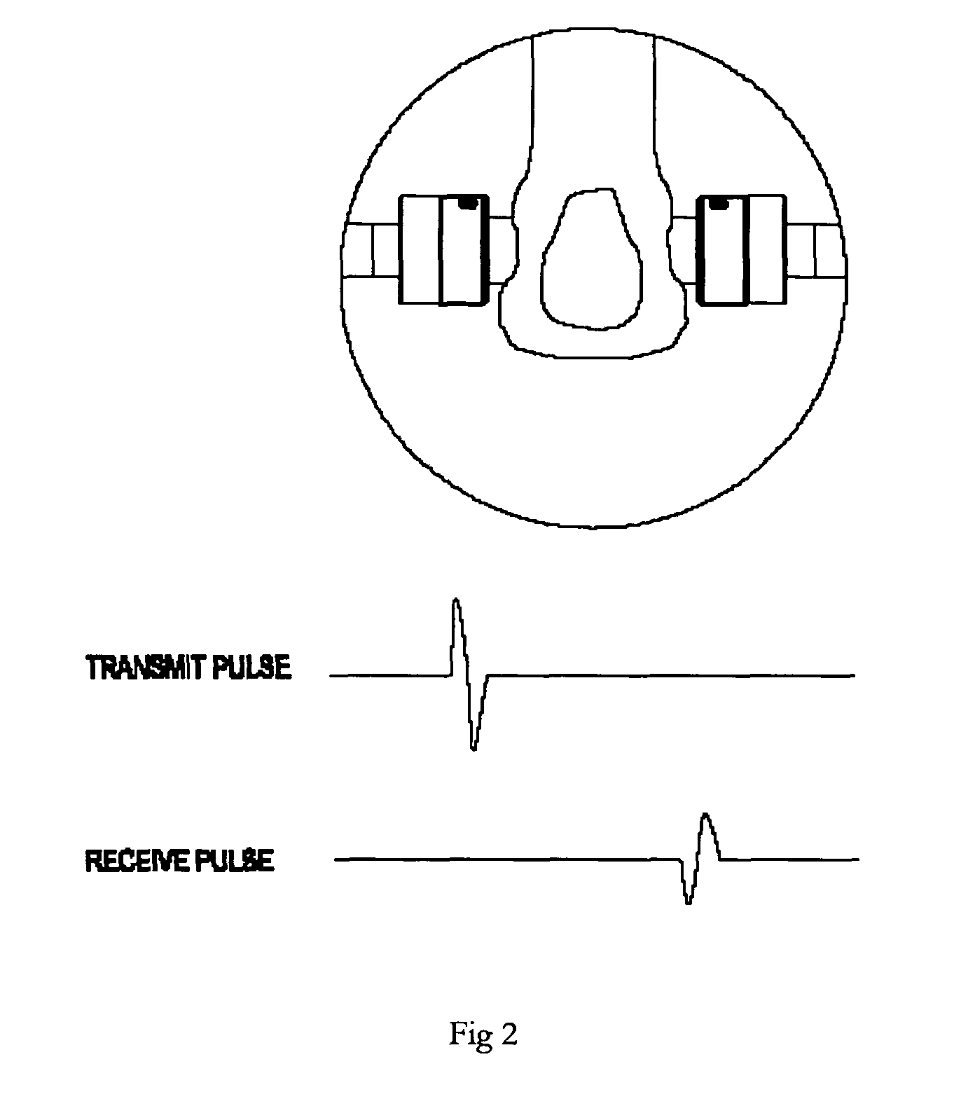
[0027]FIG. 2 shows an example of an arrangement of transducer wherein another transducer receives the ultrasound emitted by one transducer. The human body part to b...


PUM


Abstract

The present invention provides a system for improving the accuracy of the measurement of the osteoporosis condition of the human body parts especially bones using more than three parameters, viz., the broadband ultrasonic attenuation (BUA) quantity, the velocity of ultrasound (SOS) in the bone, the broadband ultrasonic back scattering (BUB) intensity, and the Width of received maximum (WORM) values are calculated from received ultrasound signals.The accuracy of each measured diagnostic parameter is improved by measuring the tissue thickness and the squish amount in the coupling pad instead of assuming constant thickness for the tissue. The several operating modes of the device are controlled and the frequency and the timing of the emitted ultrasounds signals are adjusted by using a field programmable gate array. The error generated in the measurement of the bone mineral density due to the variation in the anatomy and the size of the foot, is removed by using a removable footpad. The present invention provides a mechanism to replace the gel pads easily. The generation of cross infection is prevented by using the disposable and replaceable coupling pads.

Description

FIELD OF THE INVENTION[0001]This invention relates generally to methods and devices for assessing bone conditions, and more particularly related to a method and a device for assessing bone properties such as, for example, bone mineral density and bone micro-architecture for diagnosis of bone conditions like osteoporosis, etc using ultrasound technique.BACKGROUND OF THE INVENTION[0002]Osteoporosis is a phenomenon resulting in the weakening of the bones due to the reduction in bone mineral density and changes in the micro architecture of bone due to the depletion of minerals like calcium and bone protein. The evaluation of osteoporosis or the loss of bone minerals and the treatment or prevention of the osteoporosis is performed by usually measuring the bone density.[0003]Some of the devices used for measuring the bone density include X-ray device, gamma ray detector device and ultrasound device, etc. In general, a system used for conducting the bone analysis using the ultrasound, comp...

Claims


Application Information

Patent Timeline
Patent Type & Authority Patents(United States)
IPC IPC(8): A61B8/00
CPCA61B5/1075A61B8/0875A61B8/4281A61B5/6829
Inventor GHOSH, RAJDEEPUMADI, SOMASHEKARAGARWAL, RAJRAVINDRAN, NAGARAJANSOWMYA, MOSALE NAGESHRAO
Owner LARSEN & TOUBRO
Why Eureka
Try Eureka